Apparently they are guided by active acoustic homing, with controllable fins but no propulsion system:Nice stuff ! If they can glide underwater toward target and not just downward it make them way more effective !

You are using an out of date browser. It may not display this or other websites correctly.
You should upgrade or use an alternative browser.
You should upgrade or use an alternative browser.
PLA AEW&C, SIGINT, EW and MPA thread
- Thread starter Sczepan
- Start date
by78
General
Compared with KJ-200, KJ-500 has an embedded box on top of head radome (which makes it tilted downward). That box must house the auxiliary antenna for the calibration of top phased arrays, similar to that on a 052D destroyer.
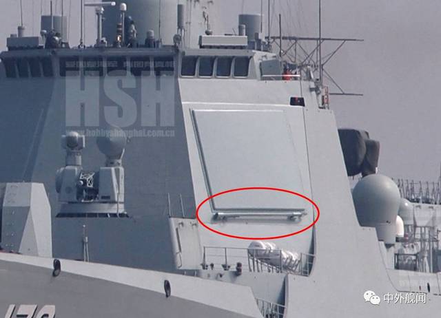

So you think the small protrusion on top of the radome (indicated by the red arrow) contains an "auxiliary antenna" for calibrating the phased arrays?

Could you explain to me how this "auxiliary antenna" is packed into such a tiny space? How it is folded and unfolded? What's the mechanism?
Since you are an expert on the efficient use of space, could you tell us how Noah was able to fit so many animals onto his , or how stores the in his ear?
Where are you from exactly? What magical realm or advanced extraterrestrial civilization do you come from? Are you like a wizard or something? Can you shrink my mother-in-law?
P.S. Have you seen the movie ? I highly recommend it!
Last edited:
by78
General
Compared with KJ-200, KJ-500 has an embedded box on top of head radome (which makes it tilted downward). That box must house the auxiliary antenna for the calibration of top phased arrays, similar to that on a 052D destroyer.
By carrying this "auxiliary antenna" onboard, I assume you believe the calibration is conducted while the plane is in the air. If so, could you explain to us how this antenna can be safely and effectively deployed while it's being buffeted by strong airflows at speeds of hundreds of miles per hour?
If you believe this "auxiliary antenna" is only used while the plane is on the ground, then may I inquire as to why you think it's wise to carry onboard a piece of equipment that will never be used inflight? Why would they deliberately waste fuel and useful payload on this dead weight?
by78
General
Compared with KJ-200, KJ-500 has an embedded box on top of head radome (which makes it tilted downward). That box must house the auxiliary antenna for the calibration of top phased arrays, similar to that on a 052D destroyer.
Woah, I think I've misread your post. By the "embedded box" on top of the "head radome", are you referring to the protrusion on the nose radome (as seen in the red circle below)?

Last edited:

The protrusion on top of the circular array of the KJ-500 should be a SATCOM, or to be more precise, a flat panel SATCOM. It contains a thin phase array on its own that communicates with satellites.
The protrusion on top of the nose of the KJ-500 should be its IFF.
The protrusion on top of the nose of the KJ-500 should be its IFF.
Hendrik_2000
Lieutenant General
Excellent documentary on Kj 500 in english It does not reveal anything new just showing the pulse production method in detail
Documentary visiting manufacture of KJ 500 China most advanced airborne early warning control plane


China's progress in Tile based Phased Array Systems
Background:
The traditional approach of slat array has a couple of advantages: it provides a large surface area on which the T/R modules and supporting components can be attached. Also, the thermal load from the high power amplifiers can be distributed across a large volume, factoring in the depth of the slat and the aperture area. The downside is that a large number of RF boards and copious cabling are required to channel the RF, DC and control signals on and off the slats. This adds considerable cost to the design.
An alternative approach—the tile array—overcomes these disadvantages through a more streamlined architecture, where the array is constructed of layers that are oriented parallel to the face (see Figure 3, MACOM). Antenna elements and RF beamformers are integrated in a single, multilayer RF board, with the T/R modules mounted on the back of the board. This approach significantly reduces the area of the RF boards and dramatically reduces the number of cables and connectors. Costs can be further reduced through the use of T/R modules designed to leverage volume-scale commercial packaging and manufacturing techniques. With this approach, the T/R module MMICs are assembled in industry standard, quad flat, no-lead (QFN) packages that are directly soldered onto an inexpensive PCB that is soldered to the back of the tile. Simple metal pads lining the edge of the PCB serve as the RF and DC interconnects between the T/R module and the back of the tile.
Comparing the relative transmit power per unit area versus the cost per unit area for the slat and tile array architectures, a greater than 5x cost reduction can be achieved with the tile array at both high power and low power outputs.
Tile-based AESAs create the foundation for such a new generation of high performance, agile radar systems that can be built quickly and cost effectively and flexibly tailored and scaled for deployment across defense, civil and commercial applications. The design and assembly techniques used for the tile array address both communications and sensing applications, enabling active antenna capability at a cost point that makes this technology viable for a wide range of commercial use cases: internet in the sky, 5G, sense-and-avoid for airborne drones and radar for autonomous vehicles
DARPA's move:
Initiated in 2014, DARPA’s Arrays at Commercial Timescale (ACT) program is designed to streamline development and manufacturing cycles for next-generation radar, electronic warfare (EW) and communications systems by leveraging best practices established in the commercial domain. It aims to achieve a digitally-interconnected phased array building block, from which larger systems can be built without a full redesign for each new application. This approach to radar system implementation is anticipated to shorten time-to-market and reduce costs, both necessary for AESAs to achieve mainstream adoption for civil and commercial applications.
A pilot project is being undertaken by MACOM with its project SPAR (Scalable Planar Array) in collaboration with MIT Lincoln Labs.
PRC's advances
An S band Tile Type Phased Array system was developed. Through the design of electromechanical and thermal integration, it breaks through the chip high-density integrated amplifier Connect, digital hybrid flow meter, multi-channel to word transceivers and other key technologies. The digital array module advances the ADC and DDS in the traditional DAM digital motherboard, and Integrated design of RF front-end and analog intermediate frequency to realize distributed digitization and centralized digital processing. It is possible to configure 4/8/16 channels flexibly for DAM; it adopts flexible connectors to complete High-speed, control, power signal interconnection / realization of 22.4Gbps high-speed data signal transmission; Use overall water cooling and local capillary heat dissipation schemes, make full use of high heat flux heat dissipation technology. The software flexibly defines the characteristics of the system function, which will be used in radar, communication, EW.
In order to meet the heat dissipation requirements of GaN power chips, a new type of heat sink material is used- Diamond copper. A micro-fin structure is added to the cooling channel of the cold plate.
Last edited: