052C/052D Class Destroyers

Zichan

Junior Member
Registered Member
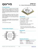
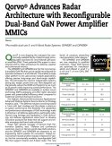
Speaking of power amplifiers, the dynamically reconfigurable S/X band HPA (7mmx6mm) from Qorvo might usher a new era of dual-band AESA radars that share the same antenna aperture to perform roles up till now delegated to two different radars:

Full article:
Please, Log in or Register to view URLs content!
 

Attachments

  • dual_band_pa_result.jpg
    dual_band_pa_result.jpg
    248.3 KB · Views: 28

tphuang

Lieutenant General
Staff member
Super Moderator
VIP Professional
Registered Member
Even if it were possible to build such a miniature radar today with 50kW output, a major challenge would be to keep it cool and feed the beast in the confined space of a fighter the size of J-20. A radar of that power might need close to half a megawatt of wall plug power to operate, possibly even more.

Just to appreciate how ludicrously powerful such a radar would be, the much feared AN/TPY-2 X-band missile defense radar is estimated to have around 25,000 T/R elements and an average transmitter power of 81 kW (radiated is less due system losses) The whole system apparently needs 2.1 MW of electrical power to operate.
I think especially with J-20B, we have to assume some level of improvement and efficiency and such. I'm clearly not in this field, but areas like thermal management system, heat exchanger system and lithium ion batteries have all improved a lot since the early 2000s. F-22 was said to have 25 kW of electrical power and 12kw of cooling back in the late 90s.

F-35 is said to be another huge jump of F-22. Doesn't seem like F-35 is fully utilizing its power. Based on your number of 25 W for top end X-Band GaN PA and if we multiply that by 2000 for J-20B (assuming it uses the most modern thermal management system available in China), that would be 50 kW in peak power and 12.5 kW in average power. That would be about 2.5x that of Irbis radar. Which seems to be a reasonable estimate and it would suffer 3db less loss on the receiving side if we were to use figures given here
Please, Log in or Register to view URLs content!
. So that would be 5 times Irbis radar's receiving power. Since power is proportional to 4th power of range, it would have 50% longer range, which maybe more in real world through better software and other technology advances.
 

Zichan

Junior Member
Registered Member
This X-band is offers 2000w peak on transmit. This either goes to a naval or land fire control radar or possibly to an airplane such as a fighter jet.
What is the size of those HPAs? Those multi-kW units appear more suitable for a PESA radar than AESA.

State of the art GaN power density at X-band is around 5-6 W/mm. To support 2kW at X-band an amplifier 40cm in size would be needed, which I think exceeds the reticle size. There are 10 W/mm devices in development, but even that couldn’t be miniaturized to fit within the confines of an AESA radar with such power output levels.
 

Zichan

Junior Member
Registered Member
F-35 is said to be another huge jump of F-22. Doesn't seem like F-35 is fully utilizing its power. Based on your number of 25 W for top end X-Band GaN PA and if we multiply that by 2000 for J-20B (assuming it uses the most modern thermal management system available in China), that would be 50 kW in peak power and 12.5 kW in average power. That would be about 2.5x that of Irbis radar. Which seems to be a reasonable estimate and it would suffer 3db less loss on the receiving side if we were to use figures given here
Please, Log in or Register to view URLs content!
. So that would be 5 times Irbis radar's receiving power. Since power is proportional to 4th power of range, it would have 50% longer range, which maybe more in real world through better software and other technology advances.
Most sources I've run across assume a 20% duty cycle for AESA radars. Therefore a 50 kW peak power transmitter would be about 10 kW average power. Furthermore, many times these figures denote the transmitter power and not the radiated power. That's something to be careful about when making comparisons. Certainly in the case of the Qorvo 25W amplifier, which still has to pass through the circulator and antenna. But a 2-3 dB difference between AESA and PESA system loss probably still holds. This page gives a nice overview of system losses in a radar, but doesn't unfortunately provide a comparison between different architectures:
Please, Log in or Register to view URLs content!


Qorvo sells more powerful X-band HPAs like the 30W QPD9300 which can operate close to 35W at the lower end of the X-band spectrum and the highest allowed drain voltage (at 25C). But these amplifiers have very poor gain compared to the 25W model: you would need to provide a 10 times larger input signal to get that power output.

Disclaimer: I am not an electronics engineer.
 

Tam

Brigadier
Registered Member
What is the size of those HPAs? Those multi-kW units appear more suitable for a PESA radar than AESA.

State of the art GaN power density at X-band is around 5-6 W/mm. To support 2kW at X-band an amplifier 40cm in size would be needed, which I think exceeds the reticle size. There are 10 W/mm devices in development, but even that couldn’t be miniaturized to fit within the confines of an AESA radar with such power output levels.

The size is stated on the link.

If I take another monster module,

Please, Log in or Register to view URLs content!

It clearly states its for active phased radar. This one has a picture of the module or they could be using image of another module as page filler.

The picture on this link does show a module with 4 circulators, which can mean 4 tx/rx channels. This means 4 hpa. The 2000w could be for 4 amps combined, which means each is 500w respectively.

Maximum power of GaN per mm is 8 watts but as early as 2007 there were papers going as far as 12 watts. In any case, to give a specific example, the Qorvo QPM1021 10 to 12Ghz 100w GaN power amp has a package dimension of 19.5 x 19.5 x 4.52mm. From 9 to 12 Ghz, the elements would have to be around 125mm to 175mm from each other. With a 600mm on one side on the 2000w module, with 4 tx channels, this puts around 150mm space between each tx, which is about right for an X-band and points to this module as a QTRM.

Here's another example, with a 500w GaN amp for S-band radar.

Please, Log in or Register to view URLs content!

Package dimensions is about 24mm x 24mm. Not much bigger than the other part.

As the specs on the Yonlit link goes it says greater than 10% duty cycle so each tx is doing 50w.

Disclaimer. Not an engineer either so you don't have to believe me.

QPM1021_Data_Sheet-1659729.jpg
 
Last edited:

Zichan

Junior Member
Registered Member
Maximum power of GaN per mm is 8 watts but as early as 2007 there were papers going as far as 12 watts. In any case, to give a specific example, the Qorvo QPM1021 10 to 12Ghz 100w GaN power amp has a package dimension of 19.5 x 19.5 x 4.52mm. From 9 to 12 Ghz, the elements would have to be around 125mm to 175mm from each other.
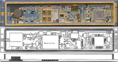
I think you forgot a decimal point: 12.5mm to 17.5 mm, assuming 0.5 lambda spacing. If you look at an example TRM module (presumably from Eurofighter Typhoon's CAPTOR-E), the HPA is only a fraction of its footprint:
1654456176561.png
Here they appear to be using two HPAs side-by-side under the heatsink? The circular device on the left is the circulator. Therefore, those Qorvo 7mmx6mm package size amplifiers appear about right in size for a dense array X-band AESA. The 19.5mmx19.5mm package is probably aimed for sparsely populated AESAs that have narrow FOVs. For a +/- 30 degree look angle, elements need to spaced at 0.67 lambda to avoid grating lobes. For a +/- 15 degree FOV just 0.8 lambda spacing is needed.

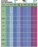
I've attached a summary of power densities of various GaN processes from the 9 manufacturers worldwide: 12W/mm has only been achieved for S-band amplifiers at the moment. There are 25W/mm X-band amplifiers in development by GCS with a GaN on diamond substrate process. The source is a September 2021 publication by the Microwave Journal.
 

Attachments

  • gan_result.jpg
    gan_result.jpg
    188.6 KB · Views: 26

Tam

Brigadier
Registered Member
I think you forgot a decimal point: 12.5mm to 17.5 mm, assuming 0.5 lambda spacing. If you look at an example TRM module (presumably from Eurofighter Typhoon's CAPTOR-E), the HPA is only a fraction of its footprint:
View attachment 90185
Here they appear to be using two HPAs side-by-side under the heatsink? The circular device on the left is the circulator. Therefore, those Qorvo 7mmx6mm package size amplifiers appear about right in size for a dense array X-band AESA. The 19.5mmx19.5mm package is probably aimed for sparsely populated AESAs that have narrow FOVs. For a +/- 30 degree look angle, elements need to spaced at 0.67 lambda to avoid grating lobes. For a +/- 15 degree FOV just 0.8 lambda spacing is needed.

I've attached a summary of power densities of various GaN processes from the 9 manufacturers worldwide: 12W/mm has only been achieved for S-band amplifiers at the moment. There are 25W/mm X-band amplifiers in development by GCS with a GaN on diamond substrate process. The source is a September 2021 publication by the Microwave Journal.

I should rephrase that to 6 cm to one side, while the other module is 5 cm.

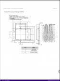
Here is the actual package size of the 500w Wolfspeed part.

Screenshot_20220606-071610_Drive~2.jpg

Without the connectors, the die and packaging (D3 x E3) is only 14 to 15mm. They may look to repackage this for a different frequency band.

As for the Captor TRM, there looks like more space under the heatsink. You got two 6mm x 7mm but the heatsink is much bigger than that. It looks it can hold a single 12mm x14mm or more like 15mm x 17mm under there. Possibly as a future option. The Wolfspeed amp can fit right into it.

As for the 19.5x19.5mm part, it can be for an AESA with mechanical assist.
 
Last edited:

Zichan

Junior Member
Registered Member
I should rephrase that to 6 cm to one side, while the other module is 5 cm.

Here is the actual package size of the 500w Wolfspeed part.

View attachment 90194

Without the connectors, the die and packaging (D3 x E3) is only 14 to 15mm. They may look to repackage this for a different frequency band.

As for the Captor TRM, there looks like more space under the heatsink. You got two 6mm x 7mm but the heatsink is much bigger than that. It looks it can hold a single 12mm x14mm or more like 15mm x 17mm under there. Possibly as a future option. The Wolfspeed amp can fit right into it.
I don't know what the size of the individual amplifiers in that TRM are. I added it as an illustration to show much extra space there is around a HPA in a typical TRM: in that example the TRM is about 4x wide as the HPA.

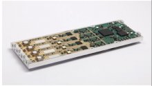
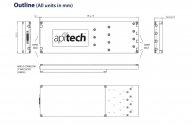
To save space, many AESAs use quad-channel TRMs, like the this tightly packed 9-10GHz GaN TRM from ApiTech:
api_quad_result.jpg
The TRM is 59.5 mm wide. At 10 GHz, to maintain a 60 degree FOV individual transmitters have to be separated by 0.54 lambda or 16.2mm. 59.5/4=14.875mm, so this TRM can fit neatly into an array with a +/- 60º FOV. The power output maxes out at only 10W, so they can use HPAs even smaller than 6mm x 7mm. I am guessing the HPAs are the beige squares that noticeably stand out from the PCB? It looks like there's easily room for 10 of them to fit side-by-side on the PCB. If I include the metal frame, about 11 should fit. Therefore, I estimate them to be between 5 and 5.5 mm in size.
api_aesa_result.jpg
They have a nice video showcasing how an array is built out of these TRMs:
 
Last edited:

Zichan

Junior Member
Registered Member
Correction for above. After pixel peeping, I determined that it is possible to layout 13 amplifiers across the TRM, therefore each measures just 4.6mm. That still seems a tad large for a 10W GaN amplifier.
 

Tam

Brigadier
Registered Member
I don't know what the size of the individual amplifiers in that TRM are. I added it as an illustration to show much extra space there is around a HPA in a typical TRM: in that example the TRM is about 4x wide as the HPA.

To save space, many AESAs use quad-channel TRMs, like the this tightly packed 9-10GHz GaN TRM from ApiTech:
View attachment 90219
The TRM is 59.5 mm wide. At 10 GHz, to maintain a 60 degree FOV individual transmitters have to be separated by 0.54 lambda or 16.2mm. 59.5/4=14.875mm, so this TRM can fit neatly into an array with a +/- 60º FOV. The power output maxes out at only 10W, so they can use HPAs even smaller than 6mm x 7mm. I am guessing the HPAs are the beige squares that noticeably stand out from the PCB? It looks like there's easily room for 10 of them to fit side-by-side on the PCB. If I include the metal frame, about 11 should fit. Therefore, I estimate them to be between 5 and 5.5 mm in size.
View attachment 90220
They have a nice video showcasing how an array is built out of these TRMs:

The long beige rectangles behind the circulators should be the HPAs, and the small beige squares that are sticking out behind the rectangles should be the phase shifters.
 
Top