You are using an out of date browser. It may not display this or other websites correctly.
You should upgrade or use an alternative browser.
You should upgrade or use an alternative browser.
052C/052D Class Destroyers
- Thread starter Jeff Head
- Start date
Hi Tam thanks for your replyJust oxidation.
How do the designers integrate all of the electronic emitters and receivers we see in this image? I imagine that interference between the various aerials must be quite a problem unless there is some magic coordinating all the electronics. I remember during the Falklands War that the HMS Sheffield type 42 of the RN was hit by an Exocet missile, here is a quote from the link below "Coventry and Glasgow’s ESM gear picked up brief radar sweeps from Argentine Super Etendards – indications of an incoming attack; Sheffield did not, as her ESM gear was blanked by her satcom system being used for a transmission." It was claimed that the ship was hit by an Exocet because it was temporarily blinded in this way. She ended up sinking.It also differs ship to ship.
Here, you see the ball like EOTS near the Sailor SATCOM. The SATCOM is to provide satellite internet.
View attachment 82293
But here the EO systems are much different. You can see four camera systems on the left and on the right side on top of the bridge, right below the perspective of the decoy launchers. I don't know what is the vintage of the ship above and but the lower one (#131) belongs to the newer batches due to the shape of the ESMs that happens to be near the camera systems.
View attachment 82294
How do the designers integrate all of the electronic emitters and receivers we see in this image? I imagine that interference between the various aerials must be quite a problem unless there is some magic coordinating all the electronics. I remember during the Falklands War that the HMS Sheffield type 42 of the RN was hit by an Exocet missile, here is a quote from the link below "Coventry and Glasgow’s ESM gear picked up brief radar sweeps from Argentine Super Etendards – indications of an incoming attack; Sheffield did not, as her ESM gear was blanked by her satcom system being used for a transmission." It was claimed that the ship was hit by an Exocet because it was temporarily blinded in this way. She ended up sinking.
HMS Sheffield did detect the incoming missile with her VHF radar, the Type 964, but failed to do a proper IFF. Thus they didn't know it was friend or foe until it was too late. It was pure incompetence.
If the instruments were interfering I would doubt that they would be placed there in the first place. PLAN ship design seems very careful with instrument placement.
The 052D's main defensive ESM are nowhere near the EOTS. They are located on the top of the spindle mast, clearing the Type 364 radar, then more are located on the side of the main mast. The SATCOMs are located to the middle and aft of the ship.
For 055 this building was used to simulate the environment of the future to be ship to work out such electronic interference issues.How do the designers integrate all of the electronic emitters and receivers we see in this image? I imagine that interference between the various aerials must be quite a problem unless there is some magic coordinating all the electronics. I remember during the Falklands War that the HMS Sheffield type 42 of the RN was hit by an Exocet missile, here is a quote from the link below "Coventry and Glasgow’s ESM gear picked up brief radar sweeps from Argentine Super Etendards – indications of an incoming attack; Sheffield did not, as her ESM gear was blanked by her satcom system being used for a transmission." It was claimed that the ship was hit by an Exocet because it was temporarily blinded in this way. She ended up sinking.
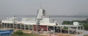
Perhaps there was something similar for 052D somewhere?
The instruments and sensors are also spaced if you look at them at a proper perspective. At the angles the other pictures are taken, they were taken with a telephoto lens, which creates a flattered perspective making things look denser than they actually are. In fact the perspective of the telephoto lens makes it appear the decoy launchers are near the IFF when they're across the ship.


Yes this picture makes your point well. The state of the art has progressed vastly over the last 20-30 years. The 55 is probably the best current example of integrating the electronics in a very clean design. Its so much more modern looking than most other designs.The instruments and sensors are also spaced if you look at them at a proper perspective. At the angles the other pictures are taken, they were taken with a telephoto lens, which creates a flattered perspective making things look denser than they actually are. In fact the perspective of the telephoto lens makes it appear the decoy launchers are near the IFF when they're across the ship.
View attachment 82920
Yes this picture makes your point well. The state of the art has progressed vastly over the last 20-30 years. The 55 is probably the best current example of integrating the electronics in a very clean design. Its so much more modern looking than most other designs.
I know this is out of topic already, but I was looking at the HMS Sheffield and how the SATCOM could have interfered with the ESM.
The SATCOM would be the small white bulb in front of the funnel, and the ESM mast is right next to it, with the antenna all the way up to make up the tallest part of the ship. For the SATCOM to have interfered with the ESM, the satellite would have to be on such a line that the ESM antenna would be between the SATCOM and the satellite. In short the satellite would have to be nearly straight up to enable the SATCOM to interfere with the ESM antenna.
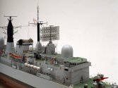
The issue of interference in the 052D might be legit but not in those two pictures. It would be on an entirely different part of the ship.
The issue is in the platform where the Type 517 VHF radar stands, which underneath are two large SATCOMs and two small SATCOMs, which are Type 366-2 datalinks. The platform is ahead of the rear VLS.

A SATCOM has a dish antenna within the dome that swivels around to track the satellite and keep the dish and its beam continuously pointed at the satellite.

Potentially if the satellite goes overhead, the dish would be facing up and so is the directed beam. That's how it would get to interfere the ESM on the HMS Sheffield.
On the 052D, the two SATCOMs are underneath the Type 517 VHF radar, so there is a potential issue of the two SATCOMs interfering with that radar if the satellite is overhead. Note on the lower ship, no. 155, which is a newer ship than no. 175, there is a new SATCOM and it is placed above the hanger instead, along with a short or Ku band SATCOM. Its possible for 155 to rely on this new SATCOM above the hanger instead of the two beneath the VHF radar.
On the new, extended 052D however, the two SATCOMs are gone underneath the new 'Fly Swatter' radar and replaced by one SATCOM over the hanger. The two SATCOMs are in a way redundant, each covers half the sky because the base of the Type 517 radar is blocking the vision, but on top of the hanger, you only need one dome because that single dome covers all 360 degrees of the sky. This improvement in the layout of the extended 052D, namely in the removal of the two SATCOMs, is kind of in a way, affirming there might be an interference issue with the two SATCOMs underneath the VHF radar.

Two small domes underneath are still retained under the Type 520 'fly swatter' radar but these are Type 366-2 datalinks, used for anti ship targeting positions from aircraft for targets over the horizon. So these datalinks are only occasionally used. As the ESM are all in the main mast of the ship, its quite in the ship and there won't be any interference unless somehow, the satellite would draw a straight line between the SATCOMs that would put the main mast in between.
Agree, very good analysis.Good analysis!


