I drew a graphic to better describe the issue, if anyone isn't familiar with ship hulls, just know that in my artistically stretched version of the research institute, in the lime circle, the ship needs to contract to form the stern. This leads to zero volume for anything other than ship machinery for the rudders and propellers.
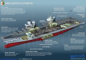
The orange box describes where the engine room of any ship, even a carrier would be generally located, the 'citadel' If this were a conventionally powered ship, the island must sit near directly above this section of the ship in order for the exhausts to work. This is why the Queen Elizabeth has two islands, and cannot use 1. It has 1 island far forward for the intakes, while the second island isn't actually very far back, it actually sits in the middle of the ship for the exhaust uptakes.

The reason why ford is capable of a optimally far rear island, is because of nuclear propulsion, the reactor's don't require exhaust cooling, and thus the island is nearly completely free to be placed anywhere upon the deck.
The illustration below includes the ship required to fit a conventionally powered engine deck where the island is located on the research institute. The drawing below is 480m long, and simply ridiculous. Oh and I calculated the displacement for fun, it'd be 175,000 tons.

The orange box describes where the engine room of any ship, even a carrier would be generally located, the 'citadel' If this were a conventionally powered ship, the island must sit near directly above this section of the ship in order for the exhausts to work. This is why the Queen Elizabeth has two islands, and cannot use 1. It has 1 island far forward for the intakes, while the second island isn't actually very far back, it actually sits in the middle of the ship for the exhaust uptakes.
The reason why ford is capable of a optimally far rear island, is because of nuclear propulsion, the reactor's don't require exhaust cooling, and thus the island is nearly completely free to be placed anywhere upon the deck.
The illustration below includes the ship required to fit a conventionally powered engine deck where the island is located on the research institute. The drawing below is 480m long, and simply ridiculous. Oh and I calculated the displacement for fun, it'd be 175,000 tons.
Last edited: