
You are using an out of date browser. It may not display this or other websites correctly.
You should upgrade or use an alternative browser.
You should upgrade or use an alternative browser.
Chinese Radar Developments - KLJ series and others
- Thread starter indochina
- Start date

by78
General
Saudi Arabia has purchased CETC's S-band surveillance radar, which can simultaneously detect and track low-altitude cruise missiles, fighter aircraft, UAVs, and other aerial targets. Detection range is reportedly greater than 20km for targets with RCS of 0.01m2.


Images from an exhibit earlier this year:
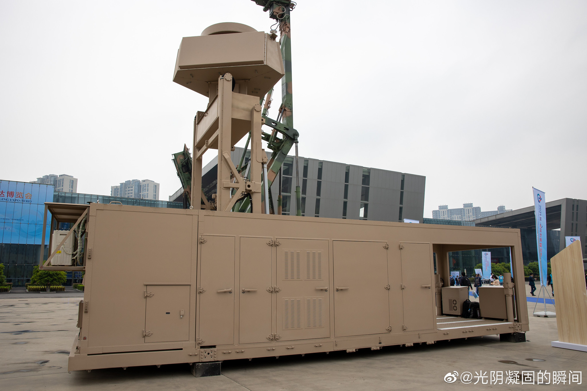


Images from an exhibit earlier this year:
===
The counterargument is that AESA is frequency agile in a way that PESA is not, since signals are generated by T/R modules under computer control, instead of being generated by a single magnetron and being phase-shifted.
In other words, AESA doesn't need IFF dipoles because it can be done via software instead of having dedicated dipoles on the face of the array. The counter example would be the F-16 with IFF dipoles built onto the sides of the radar, but the implementation, first, resembles legacy features (i.e, the F-16 had IFF systems that didn't rely on the dipole before the AESA was installed, and these weren't removed), and second, the implementation (with IFF dipoles to the side, not within the AESA) is different.
I think it's most likely that the J-10B went through a PESA phase, before transitioning off to AESA.
Let me bring this up to you again.
This old infographic describes three generations of AESA. The J-10B's radar is the one on the top. Here is described as 1.5th generation, followed by 2nd generation, followed by 3rd generation. The translation to the right points to using Gallium, I presume Gallium Arsenide, and mentions a brick packaging. The moment you mention brick packaging that's clearly an AESA as AESA modules are packaged like bricks. In fact the second radar, presumably for the J-16, also mentions a brick packaging for the T/R. Then you have the mention that the first radar is digital. In fact all three radars mentioned they were digital.

I don't understand why you say AESA doesn't need IFF dipoles because it can be done in software. The sheer problem of this is that IFF is run on the L-band 1 to 2GHz frequency or 30 to 15cm while the radar is X-band which is 8 to 12 Ghz or 3.75 to 2.4cm. You cannot do that in software. You have to do that in hardware. See the antenna below. The L-band frequency is about the length of the space between three dipoles, while the frequency of the X-band is the length of the space between three of the tiny dimples in the array. This is a physical problem.
The third radar is a stunner as it mentions using 3D MCM or 3D stacked modular chips.

Last edited:
Antenna array can use interference to drastically phase shift their frequency, but at a substantial efficiency loss. For radar applications, the efficiency loss is unacceptable, but for IFF interrogation, it's still workable.I don't understand why you say AESA doesn't need IFF dipoles because it can be done in software. The sheer problem of this is that IFF is run on the L-band 1 to 2GHz frequency or 30 to 15cm while the radar is X-band which is 8 to 12 Ghz or 3.75 to 2.4cm. You cannot do that in software. You have to do that in hardware. See the antenna below. The L-band frequency is about the length of the space between three dipoles, while the frequency of the X-band is the length of the space between three of the tiny dimples in the array. This is a physical problem.
The third radar is a stunner as it mentions using 3D MCM or 3D stacked modular chips.
Moreover, the J-10B featured both a suspected PESA and AESA array. One of the primary differences between them was that the AESA array lacked IFF dipoles. If, say, you look at other aircraft, the IFF dipoles are often located elsewhere, but if you have the aircraft completely the same, either, one, the J-10B with AESA has no IFF capability, or two, the J-10B with AESA uses its AESA to generate IFF capability.
Antenna array can use interference to drastically phase shift their frequency, but at a substantial efficiency loss. For radar applications, the efficiency loss is unacceptable, but for IFF interrogation, it's still workable.
Moreover, the J-10B featured both a suspected PESA and AESA array. One of the primary differences between them was that the AESA array lacked IFF dipoles. If, say, you look at other aircraft, the IFF dipoles are often located elsewhere, but if you have the aircraft completely the same, either, one, the J-10B with AESA has no IFF capability, or two, the J-10B with AESA uses its AESA to generate IFF capability.
No. IFF is implemented as a separate array, or an entirely separate system. It is not I repeat not a radar. It is a communication system.
The reason why IFF is implemented elsewhere is guess what, its because it is really a totally separate system. You can implement it anywhere as long as it faces the same direction as the radar.
The reason why you don't see the IFF on the J-16's and J-20's radar is because the IFF is implemented outside of the radar. The most direct implication is that a new IFF system was introduced between the first J-10B and the J-16. The J-10B without the IFF across its face, probably because a newer IFF system has been introduced to replace the old system.
There are PESA, like the later iteration of BARS, that does not have IFF dipoles across their face, so IFF dipoles have no connection to being a PESA either. The reason is that later, you got a new IFF system that can be implemented outside of the radar.
You can have mechanical parabolics with IFF dipoles across their face too, such as on the original F-15's radar. You also have slotted planars too, with and without the IFF dipoles. Again simple explanation, a newer IFF system that is implemented outside of the radar replacing the older one that has dipoles strewn across the array face.
I do not see the point of dramatically phase shifting down from X to L-band, and this will result in massive mutual coupling. This is a sort of interference where the wave from one emitter affects another emitter. In the case of an X to L-band shift, the expanded wave would affect a whole series of emitters, given the physical size of the wave (X and Y axis equal to the wavelength against the physical spacing of the elements). I do not think its acceptable because the whole array is interfering with each other. The reason why each element is spaced by half to slightly more of the wavelength is avoid mutual coupling in the first place.
It would be simpler and far more efficient to implement a separate L-band communication system to serve as the IFF.
Last edited:
We still have the underlying problem. J-10B with probable PESA vs J-10B with AESA. One doesn't have IFF dipoles on the radar.No. IFF is implemented as a separate array, or an entirely separate system. It is not I repeat not a radar. It is a communication system.
The reason why IFF is implemented elsewhere is guess what, its because it is really a totally separate system. You can implement it anywhere as long as it faces the same direction as the radar.
The reason why you don't see the IFF on the J-16's and J-20's radar is because the IFF is implemented outside of the radar. The most direct implication is that a new IFF system was introduced between the first J-10B and the J-16. The J-10B without the IFF across its face, probably because a newer IFF system has been introduced to replace the old system.
There are PESA, like the later iteration of BARS, that does not have IFF dipoles across their face, so IFF dipoles have no connection to being a PESA either. The reason is that later, you got a new IFF system that can be implemented outside of the radar.
You can have mechanical parabolics with IFF dipoles across their face too, such as on the original F-15's radar. You also have slotted planars too, with and without the IFF dipoles. Again simple explanation, a newer IFF system that is implemented outside of the radar replacing the older one that has dipoles strewn across the array face.
I do not see the point of dramatically phase shifting down from X to L-band, and this will result in massive mutual coupling. This is a sort of interference where the wave from one emitter affects another emitter. In the case of an X to L-band shift, the expanded wave would affect a whole series of emitters, given the physical size of the wave (X and Y axis equal to the wavelength against the physical spacing of the elements). I do not think its acceptable because the whole array is interfering with each other. The reason why each element is spaced by half to slightly more of the wavelength is avoid mutual coupling in the first place.
It would be simpler and far more efficient to implement a separate L-band communication system to serve as the IFF.
So which is it? The J-10B had a completely superfluous IFF dipole system, or the J-10B with AESA ran without IFF dipoles?
We still have the underlying problem. J-10B with probable PESA vs J-10B with AESA. One doesn't have IFF dipoles on the radar.
So which is it? The J-10B had a completely superfluous IFF dipole system, or the J-10B with AESA ran without IFF dipoles?
IFF simply has nothing to do with the radar itself. You can have PESA with IFF and PESA without IFF. You can have AESA with IFF and AESA without IFF. You can have mechanical parabolic or cassegrain with IFF and without IFF.
The IFF is a separate system attached to the radar as an accessory. You can put it somewhere else.
Without it on the radar you simply placed it somewhere close by. A good place is to put it is in the top of the nose.
This is such a simple concept.
If you don't see the IFF dipoles on the array, it can mean its somewhere in the rest of the plane.
I believe the example of IFF on the top of the nose is the F-16V, correct? those slotted arrays?The IFF is a separate system attached to the radar as an accessory. You can put it somewhere else.
Without it on the radar you simply placed it somewhere close by. A good place is to put it is in the top of the nose.
This is such a simple concept.
If you don't see the IFF dipoles on the array, it can mean its somewhere in the rest of the plane.
I believe the example of IFF on the top of the nose is the F-16V, correct? those slotted arrays?
Block 52 and above. Its a set of dipoles.
Hendrik_2000
Lieutenant General
China is closer to Quantum radar according to paper publish in journal of radar
Stephen Chan
Published: 10:00am, 3 Sep, 2021
A new quantum developed by Chinese scientists could detect stealth aircraft by generating a small electromagnetic storm, according to the researchers.
Most radars are known for having a fixed or rotating dish, but this quantum radar looks more like a gun and could accelerate electrons to almost the speed of light. The electrons, after going through a winding tube in extremely strong magnetic fields, could produce a vortex of microwaves that barge forward like a tornado.
The new quantum radar would be more sophisticated than any previous radar systems and building it would not be an easy job, said Professor Zhang Chao and his team at Tsinghua University’s aerospace engineering school in a paper in Journal of Radars, a Chinese peer-reviewed publication, on Tuesday.
But “the better the stealth technology, the higher the gain” of the new quantum radar would be, they said.
Chinese team says quantum physics project moves radar closer to detecting stealth aircraft
- Quantum particles in a man-made electromagnetic storm bounced back after hitting stealth object, increasing chance of detection, according to scientists
- The Tsinghua University researchers are seeking an industrial partner to build a full-sized prototype
Stephen ChanPublished: 10:00am, 3 Sep, 2021
A new quantum developed by Chinese scientists could detect stealth aircraft by generating a small electromagnetic storm, according to the researchers.
Most radars are known for having a fixed or rotating dish, but this quantum radar looks more like a gun and could accelerate electrons to almost the speed of light. The electrons, after going through a winding tube in extremely strong magnetic fields, could produce a vortex of microwaves that barge forward like a tornado.
The new quantum radar would be more sophisticated than any previous radar systems and building it would not be an easy job, said Professor Zhang Chao and his team at Tsinghua University’s aerospace engineering school in a paper in Journal of Radars, a Chinese peer-reviewed publication, on Tuesday.
But “the better the stealth technology, the higher the gain” of the new quantum radar would be, they said.