055 DDG Large Destroyer Thread

Status
Not open for further replies.

GTI

Junior Member
Registered Member
Can you clarify what you mean by a reduced quality firing solution and what causes it?

If your aim is off, then no matter what the ROF is, you won’t hit the target.
A LRASM?

Tbh, I thought it was nonsense when I first saw it, but he may have a point (admittedly I probably don’t know enough about CIWSs and targeting radar).

The assumption would be that a DEW would be aimed at a single point, RAM-type point defence missiles would need a quality track and FS, whereas a monster CIWS could lay down “boxes of lead” at where the target is approximated to be?

Again, I’m just postulating and positing… be kind…?
 

nlalyst

Junior Member
Registered Member
A LRASM?

Tbh, I thought it was nonsense when I first saw it, but he may have a point (admittedly I probably don’t know enough about CIWSs and targeting radar).

The assumption would be that a DEW would be aimed at a single point, RAM-type point defence missiles would need a quality track and FS, whereas a monster CIWS could lay down “boxes of lead” at where the target is approximated to be?

Again, I’m just postulating and positing… be kind…?
These 30 mm gun CIWS have an effective range of 1.5km - 2km. Unless the Americans have undisclosed Area 51 cloaking technology, pretty much every modern combined radar and optical targeting C-RAM system should be able to lock onto a VLO missile from that range.

I suspect it might rather be a limitation of the gun system to lay accurate/dense enough fire at high speed incoming missiles. Unlike a DEW, a cannon is subjected to strong vibrations while firing which causes small variations in placement of shells. This is not the only source of error in the gun, of course. Thermal expansion, shell variations, etc come into play as well. However, as long as the control system can keep the deviations within a small defined circle, the higher the ROF the larger the probability that a shell hits the incoming missile, which could otherwise slip through if the density of shells within the engagement cone was too low.

A Mach 3 missiles moves at 1km/s: at that speed, a 30mm CIWS might have just 1.5s of effective firing time, assuming engagement in the range [500m - 2000m].

A DEW can begin effecting the missile from a significantly longer range. If an optical targeting system can keep a lock on the target, a laser can hit it. Unlike a shell moving at Mach 3, which takes 2s to reach 2km, by which time a Mach 3 missile would also move 2km, a laser will hit the target practically instantaneously at such range.
 
Last edited:

Lethe

Captain
The 20-barrel gatling gun may be a mere technology or rather engineering demonstrator for the "dual firing" mechanism, or it may indeed be a response to a specific PLA(N) requirement intended to reach operational status and succeed or complement Type 1130 as a further improved CIWS. Here are the challenges I see in relation to the latter prospect:

1) Cost. It is safe to assume that the cost of the system is increasing as the number of barrels and feed systems increase.
2) Weight. It is safe to assume that weight is increasing as additional barrels and feed systems are added, coupled with greater quantities of ammunition to offer a similar number of "bursts", and the corresponding structures to support those elements may also require reinforcement. Increased weight and volume (through-deck penetration) can create challenges for mounting on existing ships, but just as significant the increased weight of the system gives it more inertia which makes it more difficult to achieve the correct orientation/elevation to engage the inbound both quickly and precisely. That is to say, there may actually be a reduction in certain aspects of system performance.
3) Reliability. As the number of components in the system increases, the likelihood of failure increases.

And ultimately, of course, you are still looking at the same kind of system with the same inherent limitations of range and projectile time of flight.

That is not to say that this 20-barrel dual-firing system, or some other mechanical improvement to existing gun-based CIWS can't or won't happen, but in my view those are the challenges that have to be overcome.
 
Last edited:

Maikeru

Captain
Registered Member
A LRASM?

Tbh, I thought it was nonsense when I first saw it, but he may have a point (admittedly I probably don’t know enough about CIWSs and targeting radar).

The assumption would be that a DEW would be aimed at a single point, RAM-type point defence missiles would need a quality track and FS, whereas a monster CIWS could lay down “boxes of lead” at where the target is approximated to be?

Again, I’m just postulating and positing… be kind…?
Is there any reason a DEW cannot move its aim-point around rapidly within a small given area t achieve the same effect as a shell "box"? Obviously not as efficient as aiming directly at the target but with a sufficiently powerful laser (or whatever) could work?
 

Richard Santos

Captain
Registered Member
Can you clarify what you mean by a reduced quality firing solution and what causes it?

If your aim is off, then no matter what the ROF is, you won’t hit the target.

If the solution quality is known to be less than desired, a higher rate of fire would allow the fire control to more effectively compensate by moving the aim point about the approximate location of the target while spraying bullets.
 

nlalyst

Junior Member
Registered Member
I don't know why its narrow if it can be considered narrow on the 052D. Perhaps it doesn't need to interrogate as many aircraft as the Shandong, and there are power, weight, electrical infrastructure, EM interference constraints that you do not need the device to be more than the intended mission.

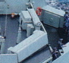
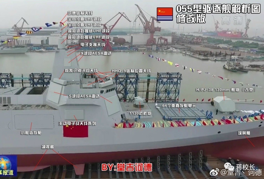
On the 055, those things look too big just for HQ-9 communication. My speculation is that the book ends of the system are for HQ-9 communication, with the bridge between the bookends being the IFF interrogator. There are actually eight bars around the top of the superstructure, the four above the radars are the thick ones, and you got another four in the between. The between ones however are too thin when compared to the Type 346A IFF bars, and furthermore they feature a back end structure whereas the other IFF bars doesn't. The 4th bar is visible from the back of the superstructure. You have the thin set about 12, 3, 6, and 9 o'clock of the ship, and the big thick ones about 45 degrees of each diagonal from the ship's axis. Could this be another radar set or another IFF set?
The ones facing 12,3,6,9 look in width comparable to the panels on the Type 052D. I would wager that these are the IFF. If they worked on the Type 052D, they should work on the Type 055.

An argument I've heard from Henri K in favor of the larger panels being IFF is the reportedly significantly higher performance of the Type 346B radar. On the face of it, that seems sound. However, I see two problems with that.

1. IFF typically operate at much longer wavelengths: the USN's IFF operates at 1030-1090 MHz. That's 6-8 times lower frequency compared to C-band used to communicate with the HQ-9 missiles. I will assume that PLAN's IFF similarly operates at comparable UHF frequencies (do you have more precise data?): 1GHz UFF vs 7 GHz comm link.

Even in typical clear weather, we are looking at 2-5 times more specific signal attenuation at 7GHz versus 1 GHz (db/km) (exact numbers depend on water vapor content in the air). If we add moderate rain into the picture, the ratio can widen to over 100 times the difference, with fog and clouds to 1000 and in heavy rain to over 10,000 times (for the duration of the atmospheric disturbance).
Take a look at these graphs:
Please, Log in or Register to view URLs content!


Let's assume that HQ-9Bs have a range of about 250km. Let's also assume both antenna have equal output power and gain. In perfect weather conditions, the Type 346B should have an instrumented range of at least 250*3.5=875km to justify using a more powerful antenna for IFF. However, against a target flying at 10km its theoretical radar horizon is roughly 415km. Even against a target flying at 15km, it's still just 500km.

Of course, the calculus changes if the C-band array is allowed to have more radiating power and gain, which might be the case if they are both AESAs.

2. If those are the IFF, where are the C-band missile comm antennas? Still embedded in the Type 346B radar?

6d0e4d765d5a4027a4f41a872c890292_th.jpg
 
Last edited:

Tam

Brigadier
Registered Member
The ones facing 12,3,6,9 look in width comparable to the panels on the Type 052D. I would wager that these are the IFF. If they worked on the Type 052D, they should work on the Type 055.

An argument I've heard from Henri K in favor of the larger panels being IFF is the reportedly significantly higher performance of the Type 346B radar. On the face of it, that seems sound. However, I see two problems with that.

1. IFF typically operate at much longer wavelengths: the USN's IFF operates at 1030-1090 MHz. That's 6-8 times lower frequency compared to C-band used to communicate with the HQ-9 missiles. I will assume that PLAN's IFF similarly operates at comparable UHF frequencies (do you have more precise data?): 1GHz UFF vs 7 GHz comm link.

Even in typical clear weather, we are looking at 2-5 times more specific signal attenuation at 7GHz versus 1 GHz (db/km) (exact numbers depend on water vapor content in the air). If we add moderate rain into the picture, the ratio can widen to over 100 times the difference, with fog and clouds to 1000 and in heavy rain to over 10,000 times (for the duration of the atmospheric disturbance).
Take a look at these graphs:
Please, Log in or Register to view URLs content!


Let's assume that HQ-9Bs have a range of about 250km. In perfect weather conditions, the Type 346B should have an instrumented range of at least 250*3.5=875km to justify using a larger antenna for IFF. However, against a target flying at 10km its theoretical radar horizon is roughly 415km. Even against a target flying at 15km, it's still just 500km.

2. If those are the IFF, where are the C-band missile comm antennas? Still embedded in the Type 346B radar?
Let's take this shot.

51186629868_e5ade7f8b1_k.jpg


The design of the larger bars look like this.

[ ]======[ ]

There are two book ends on the sides, or its thicker on the sides.

iff4.png

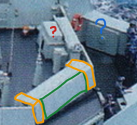
My hunch is that the book ends, the ones I marked in gold, are the HQ-9 datalinks.

iff5.png

The green part is the IFF itself. The length of the actual IFF itself is shorter than the entire bar because the ends of the bar are the C-band communication antennas. They look like its a single long array but that's only the cover.

I will point out that this bar has segmented design, and if you have seen IFF before, the antenna is divided into segments. The IFF on the 052D is also divided into a similar number of segments.

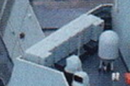
iff1.png

You can see that the book ends is a different device from the bar and have their own air circulation at the back.

As for the bars at the 12, 3, 6 and 9 o'clock locations, there is something on back of them (red ?) that I don't see on the 052D IFF. This is a new device or a new design, or to the very least its not the same. You can check the 052D here.

46381367515_4c56d97748_o.jpg

Blue ? is another puzzle as they are set on all four corners of the bridge wing. These are set on 45 degree positions from the ship. These are also my datalink candidates.
 
Last edited:

nlalyst

Junior Member
Registered Member
...
@Deino
Why is the discussion about Type 055 sensors off topic in the Type 055 thread?
 
Last edited by a moderator:
Status
Not open for further replies.
Top