052C/052D Class Destroyers

Tam

Brigadier
Registered Member
That's because the story takes place in the early to mid 2000s, more than 10 years ago. Also, I don't think quad packed TRs were top tier products even back then.

What I was trying to establish is an upper bound for transmitted RF power on the assumption the radar is air cooled. Using the total antenna surface is not unreasonable, given that the panel also serves to transmit the heatload to a heatsink. Obviously, there will be hotspots around the power amps of TR elements and any real cooling solution needs to ensure that those don't exceed design thresholds. However, given that we know next to nothing on the actual panel composition we cannot even start making a model for that.

Therefore, a comparative study. I picked the AN/TPY-2 not because it's X-band, but because it's a high power AESA radar whose many operational parameters are publicly available. If you happen to have similar data on a S-band AESA, that would be even better. Perhaps we can apply a multiplicative factor to account for the fact that cooling an S-band is likely easier than X-band due to lower power density.

Using the total antenna area is incomplete, because the front part is only the surface area of one dimension, since you need to consider the total surface area of all three dimensions of the module. In fact, more cooling can be done and needs to be done on the middle or the back than on the front part, as this might place the module's amp. Another is that the modules transfer heat to the frame of the plank, and then the sub array frames. That's why the packaging is critical. And then the air can be cooled, and what temperature can the air be cooled and the environment can be thermostatically and variably be controlled. Each module can have heat sensors that can also switch the cooling systems on. We don't know about the efficiency of the cooling systems therein.
 
Last edited:

Max Demian

Junior Member
Registered Member
Using the total antenna area is very incomplete, because the front part is only one dimension, since you need to consider all three dimensions of the module. In fact, more cooling can be done and needs to be done on the back than on the front part, as the back part would feature the module's amp. Another is that the modules transfer heat to the frame of the plank, and then the sub array frames. That's why the packaging is critical. And then the air can be cooled, and the environment can be thermostatically controlled. Each module can have heat sensors that can also switch the cooling systems on.

See my follow-up post where the module cross-section is taken into account.
 

Tam

Brigadier
Registered Member
Continuing post #3119

I decided to directly apply the pasted formula from the book Radar Systems and Analysis. This formula takes into account the module cross-section as function of lambda.
I used the following parameters for Type 346:
N_e = 5000
H_d = 2kW/m2 (max allowed heat density using air cooling at sea level)
eta = 0.2 (efficiency)
lambda = 0.09m (roughly corresponding to 3.3GHz)

The calculated max allowed average power comes out to roughly 10 kW per radar face. This will linearly scale with the number of elements and quadratically with the wavelength.

Again, you are not considering the use of the air itself being cooled, even refrigerated, thermostatically controlled environments, packaging factors, the planks and subarrays.

This might give a better idea what's behind the antenna. Also note the antenna as it is a notched type, which gives greater surface area than a plated type.

 
Last edited:

Max Demian

Junior Member
Registered Member
Again, you are not considering the use of the air itself being cooled, even refrigerated, thermostatically controlled environments, packaging factors, the planks and subarrays.

I encourage you then to come up with an alternative calculation of your own.

I am trying to produce an estimate based on what is known or claimed (Wiki article). What you're suggesting sounds a lot like phase change cooling. But if it's more akin to air conditioning then that's fine.

When I was younger, I did quite a bit of CPU overclocking, so I know that it's possible to go over 2kW/m2 with air-cooling when allowing for up to 70K increase over ambient. However, I was using 600g heatsinks (not including fan weight) to cool a 150mm2 chip embedded within a 1.4cm2 heatspreader LGA package. I don't think that would scale to something the size of a Type 346 :D

Here's a nice article to start making further estimates along these lines:
Please, Log in or Register to view URLs content!
 
Last edited:

Max Demian

Junior Member
Registered Member
Continuing post #3124

Correction for heatspreader size: 14cm2 instead of 1.4 cm2 (actually a bit less, as the heatspreader doesn't cover the entire socket area).

To continue on Tam's remarks, and to understand what is possible, an Arleigh Burke flight IIA has an equivalent of five 200 ton AC plants installed. According to this article:
Please, Log in or Register to view URLs content!
, peak power consumption is about 0.75kW per ton which comes out to 800kW for AC alone. Unknown how much of that can be dedicated to radar equipment cooling. For flight III, they are upping that to 1500 tons total equivalent AC mostly on account of needing to cool the new SPY-6 GaN AESA.
 
Last edited:

Tam

Brigadier
Registered Member
I encourage you then to come up with an alternative calculation of your own.

I am trying to produce an estimate based on what is known or claimed (Wiki article). What you're suggesting sounds a lot like phase change cooling. But if it's more akin to air conditioning then that's fine.

I found some pictures though its not the exact ones I remember. However, this kind of tubing is something I would associate more for liquid instead of air, and starting to make me question if the "air cooled" entry on Wiki is correct.

When I was younger, I did quite a bit of CPU overclocking, so I know that it's possible to go over 2kW/m2 with air-cooling when allowing for up to 70K increase over ambient. However, I was using 600g heatsinks (not including fan weight) to cool a 150mm2 chip embedded within a 1.4cm2 heatspreader LGA package. I don't think that would scale to something the size of a Type 346 :D

Here's a nice article to start making further estimates along these lines:
Please, Log in or Register to view URLs content!

Similar but the module is also transferring heat to the plank or sub array. The PC CPU does not transfer heat to the PC frame.

Test ship 891 with Type 346, with exposed plumbing.

1299066512_87699.jpg 891-346.jpg

Author of this page thinks its water cooled. He wrote this back during early 2013.

0061_vppilo_fg.png
 
Last edited:

asif iqbal

Lieutenant General
overall 13 x Type 052D and 4 x Type 052DL total 17 in the water

3 more under construction at DL and 4 at JNCX

thats 24 units of Type 052D/L identified
 

by78

General
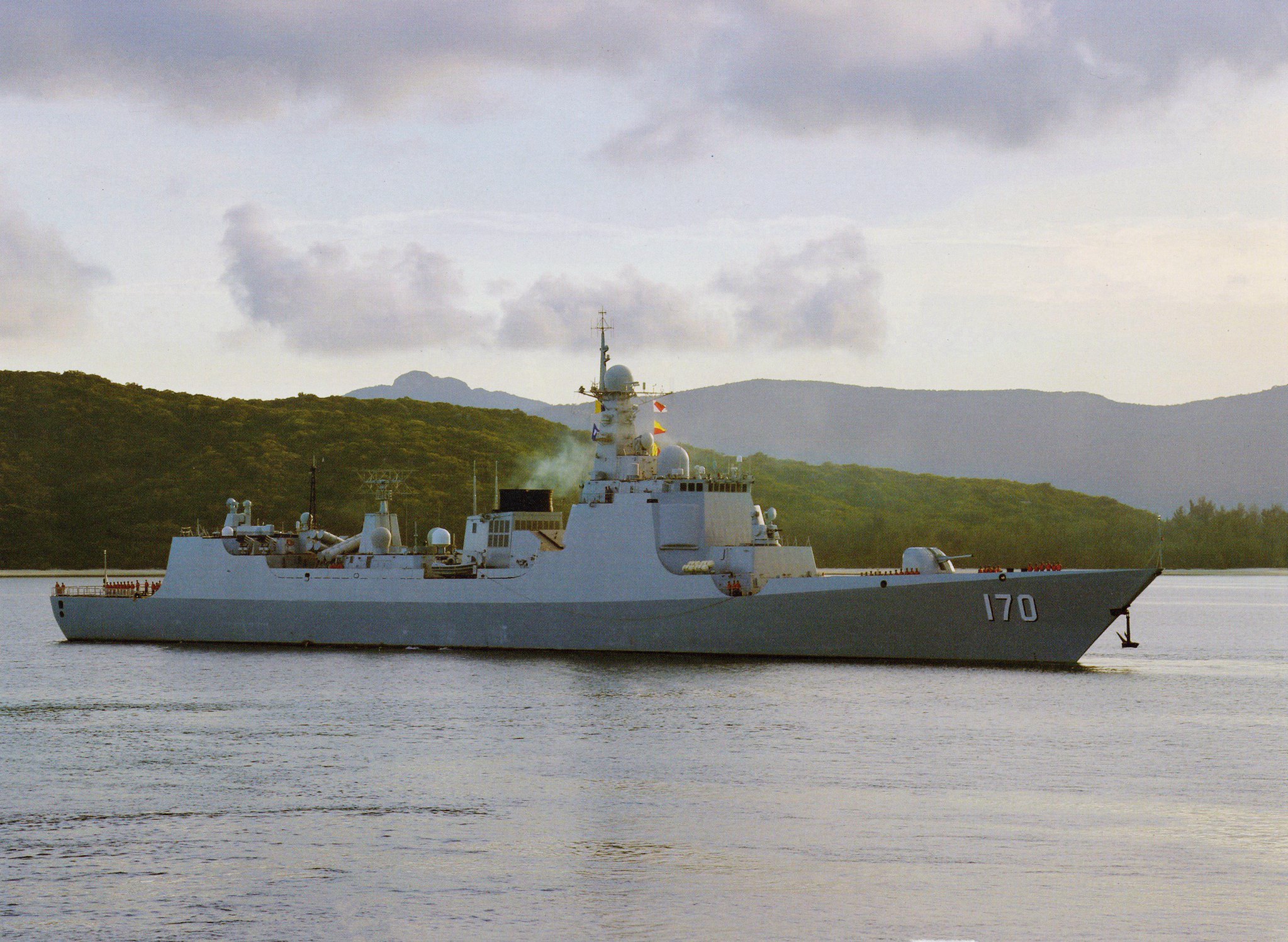
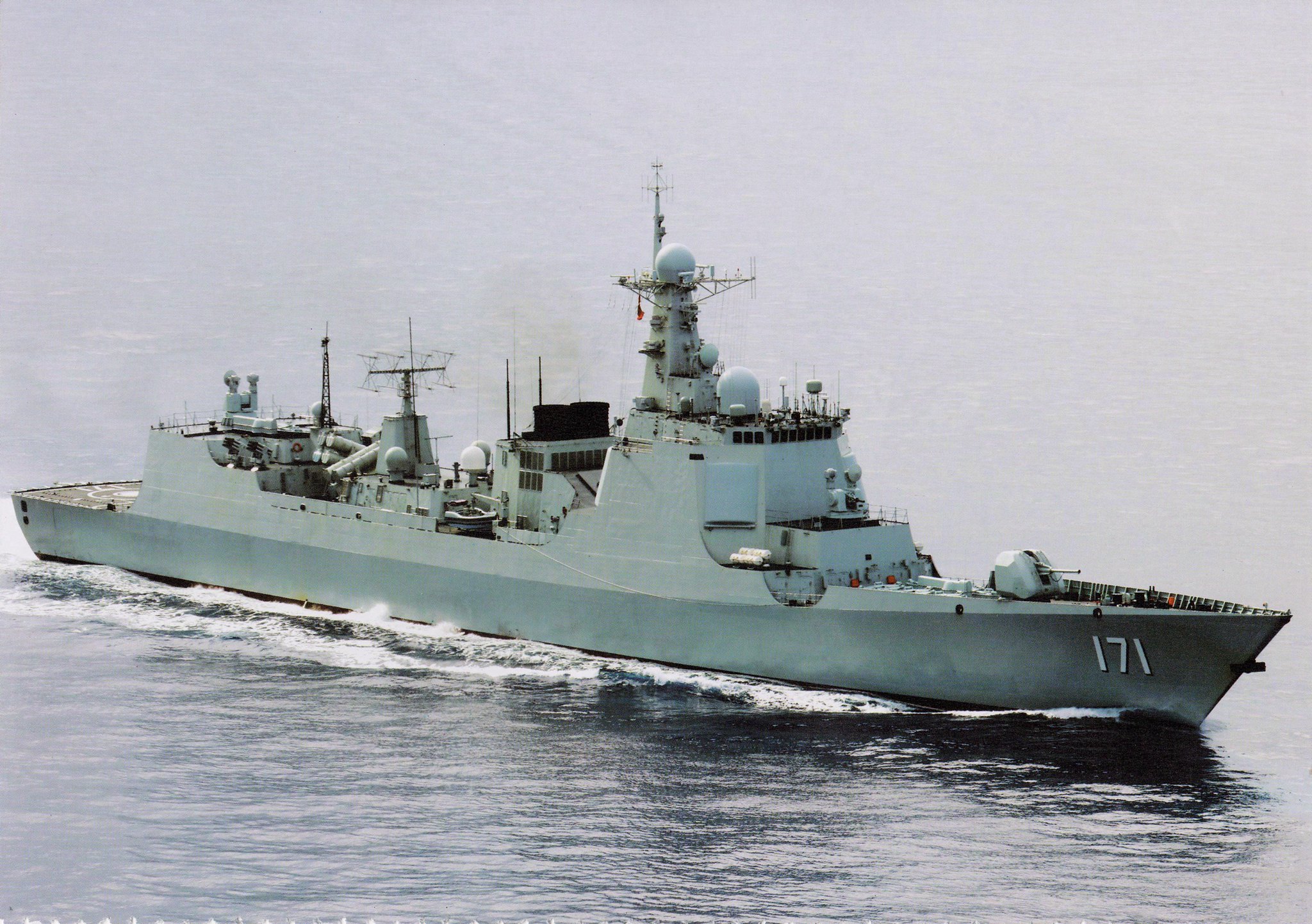
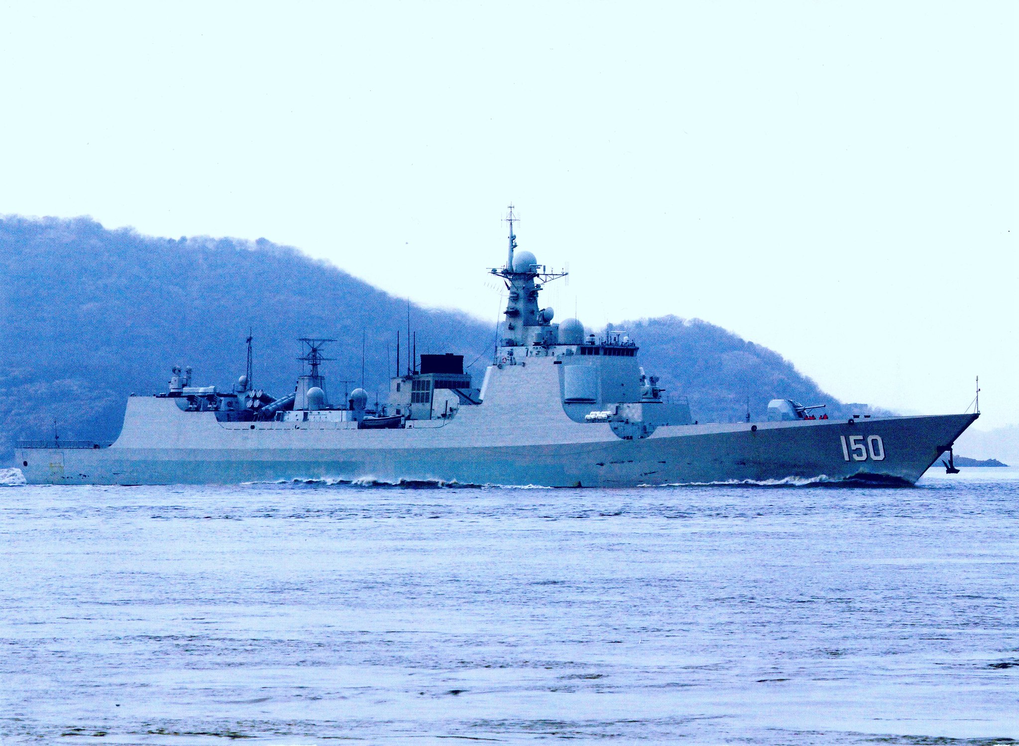
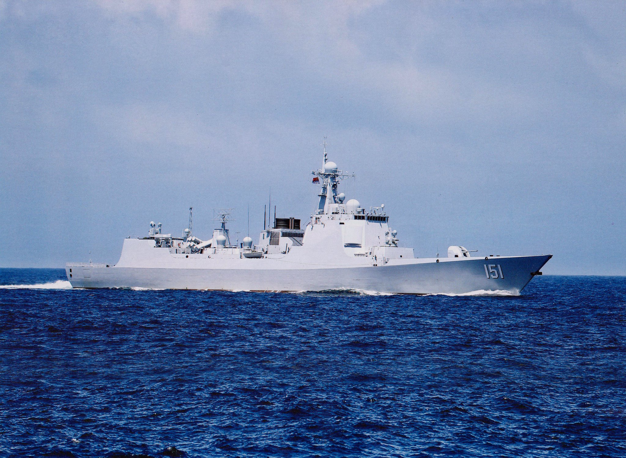
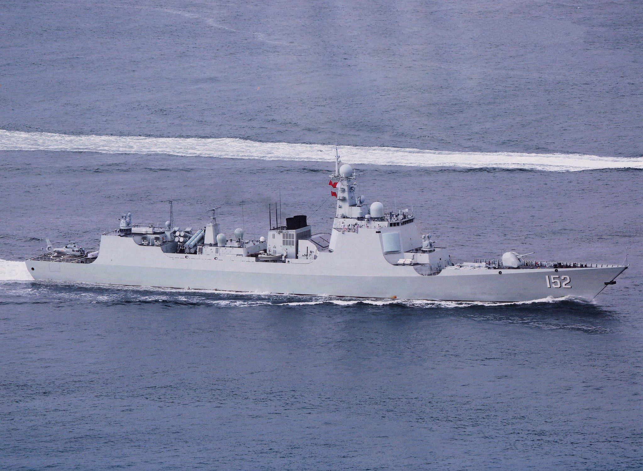
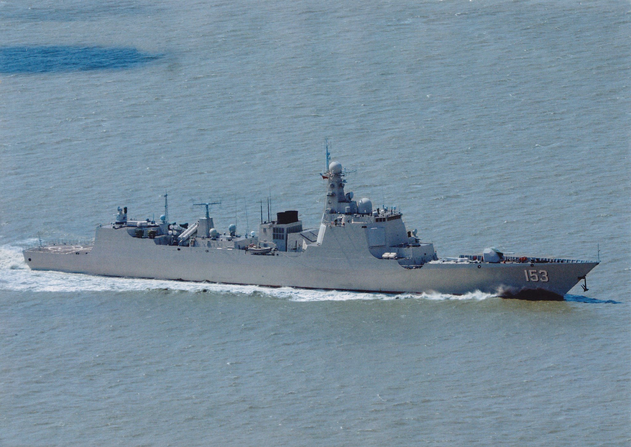
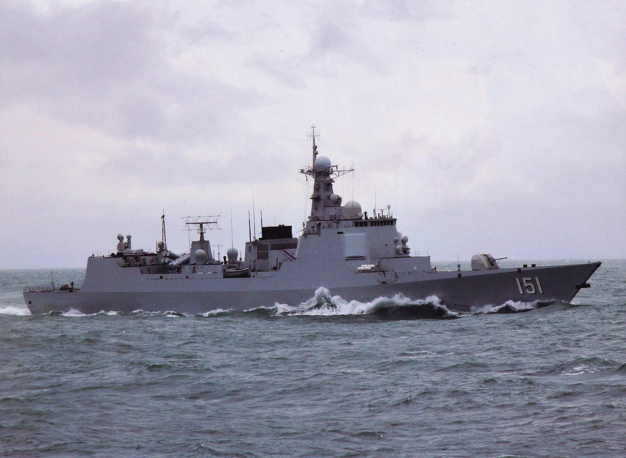
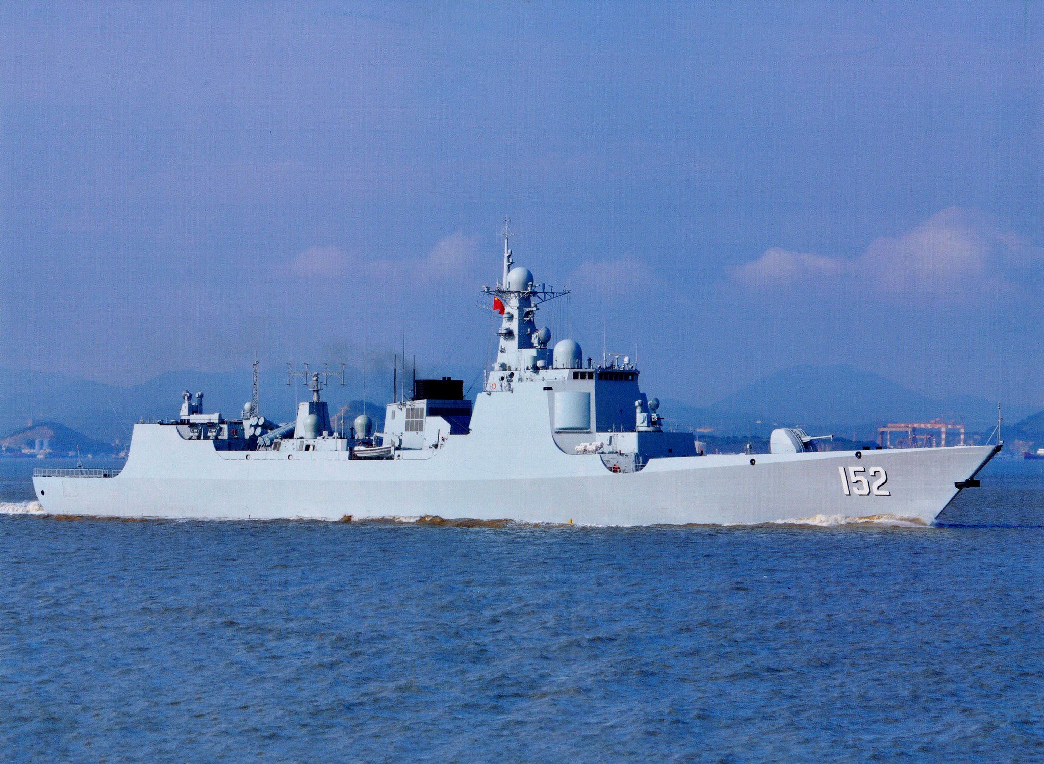
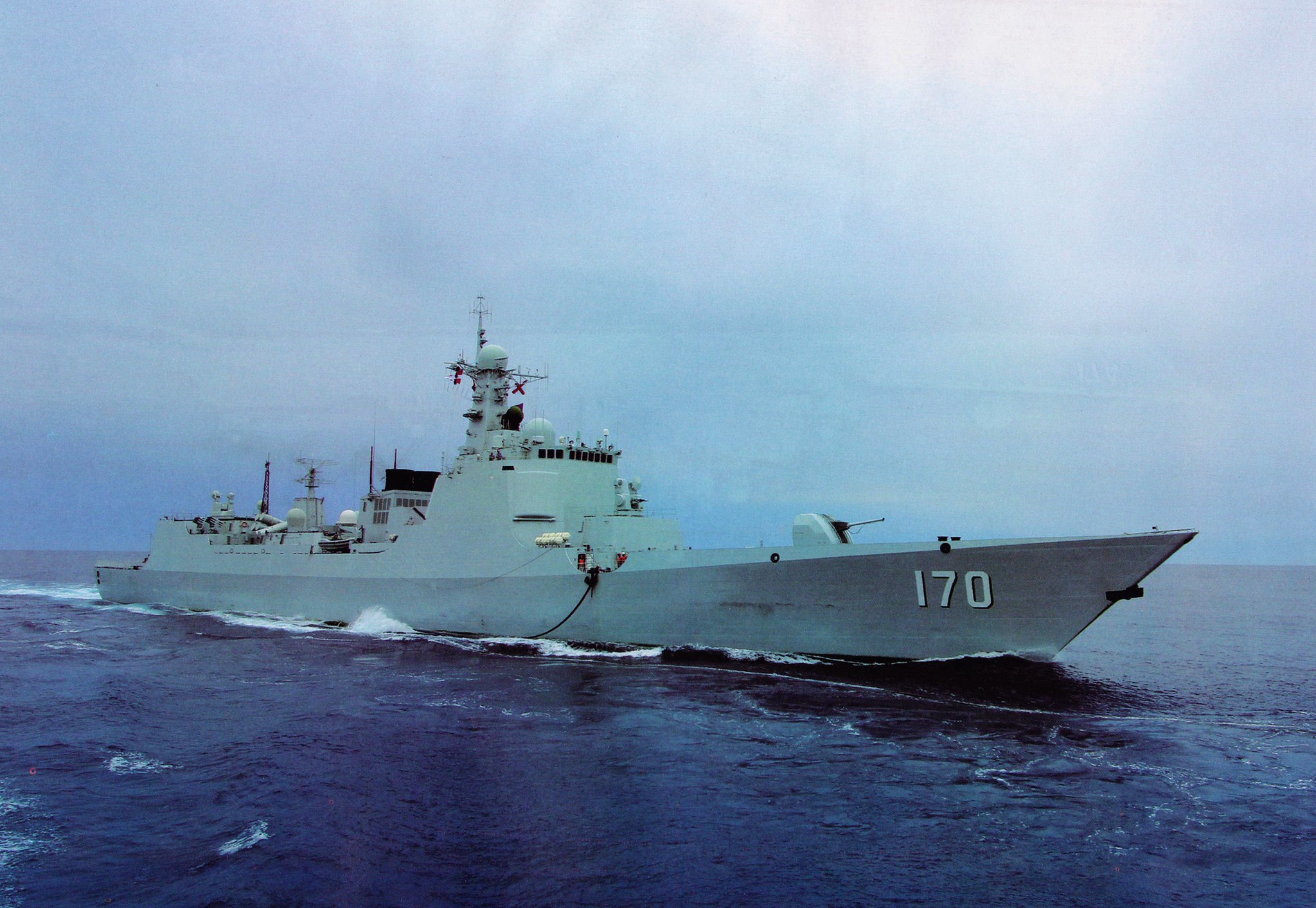
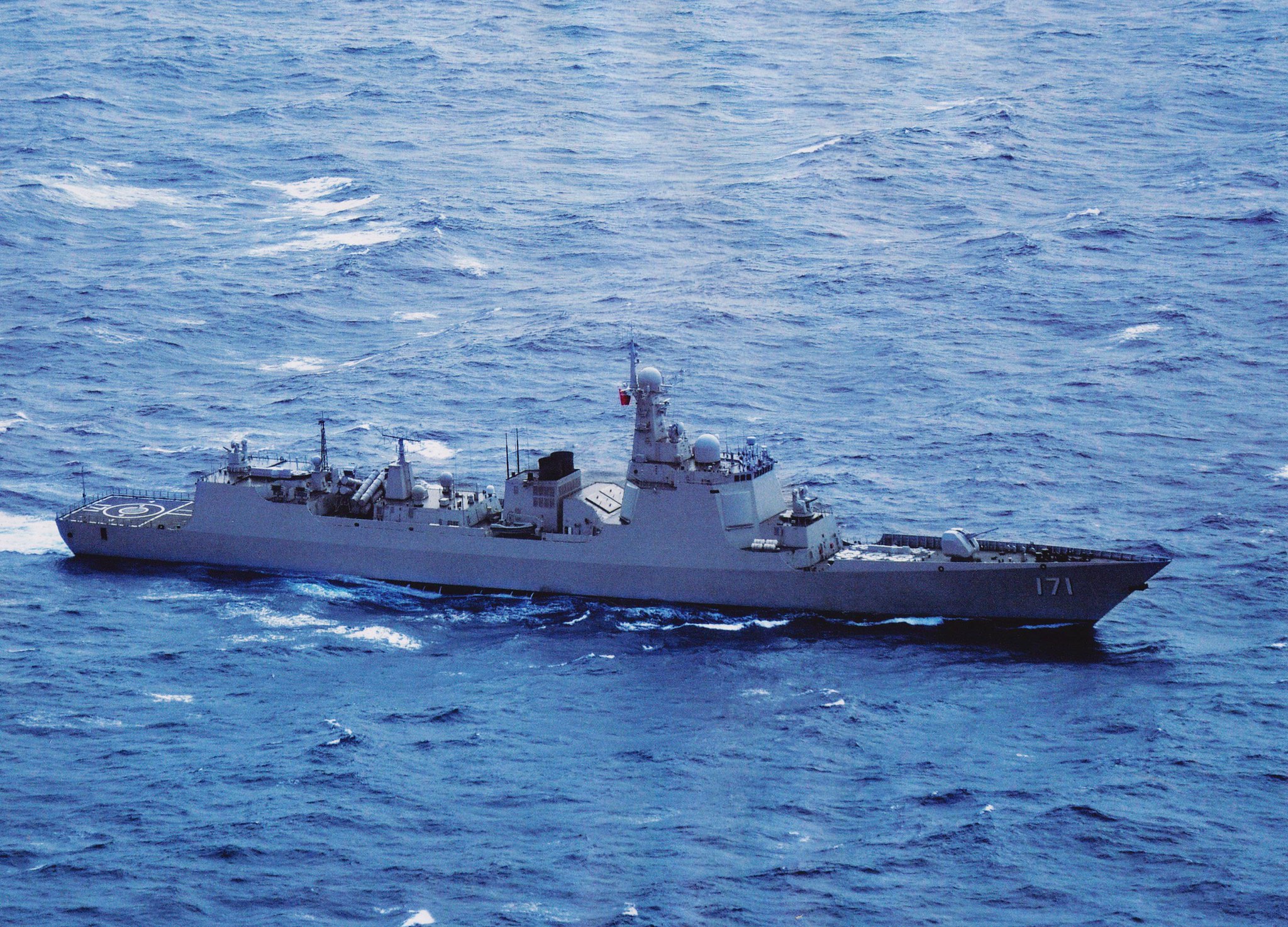
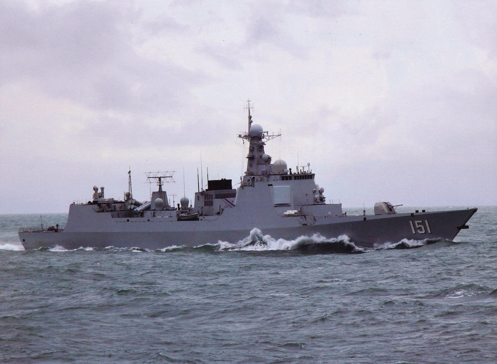
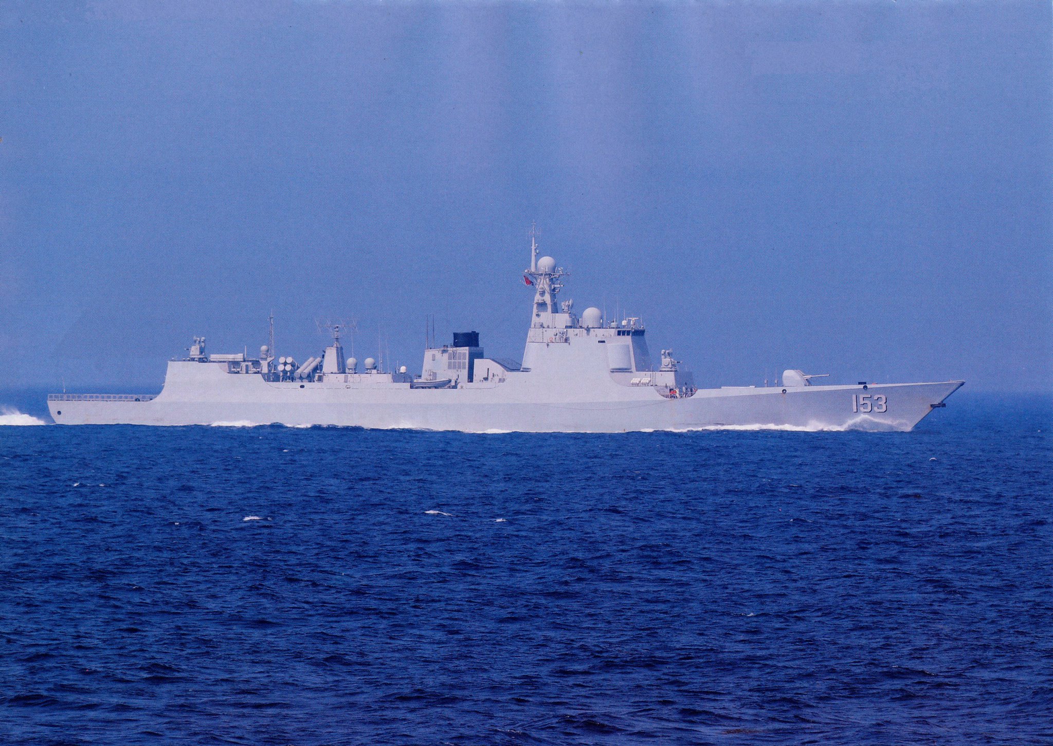
High-resolution images of various 052C and 052D units of PLAN... Some of these are old, but I'm reposting them here due to Flickr losing a lot of my photos after it migrated servers...

47368166012_fcc3f62ae3_o.jpg

32479236887_ad354e6e62_k.jpg

46698089494_25c3754883_k.jpg

32479238087_22d5a79108_k.jpg
 
Top