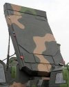
052C/052D Class Destroyers

Franklin

Captain
According to Janes Defense Type 052D destroyer 119 Guiyang and another Type 054A frigate 542 Zaozhuang has entered PLAN service in late february.

Type 052D destroyer and Type 054A frigate enter service with PLAN

Photographs circulating on Chinese social media indicate that a Type 052D (Luyang III-class) destroyer (pennant number 119) and a Type 054A (Jiangkai II-class) frigate (pennant number 542) were commissioned in late February.

Accompanying comments said the ships were named Guiyang and Zaozhuang, respectively, and state that they entered service with the People's Liberation Army Navy's (PLAN's) North Sea Fleet on 22 February.

The Type 052D destroyers displace over 7,000 tonnes and are 157 m in length. Sixty-four vertical launch tubes, which can fire HHQ-9 surface-to-air missiles and the anti-ship variant of the YJ-18A long-range cruise missile, are installed in two grids: forward and midships.

The lead shipyard for building the Type 052D is Jiangnan Changxingdao, where the first of class was launched in August 2012. However, Guiyang - the eighth Type 052D to be launched overall - was the first to be built by the Dalian Shipbuilding International Company (DSIC). The vessel first entered the water in November 2015, with two further Type 052Ds launched by DSIC in August 2016 and June 2017.

Unconfirmed reports state that the 17th overall Type 052D destroyer was launched at Jiangnan on 23 February, where three more ships of the class are being fitted out post-launch.

Zaozhuang , is the PLAN's 30th Type 054A frigate and appears to be the final ship of the class. It was the 15th to be built at the Huangpu shipyard in Guangzhou, with the remainder being constructed at the Hudong-Zhonghua shipyard in Shanghai.

Please, Log in or Register to view URLs content!
 

Tam

Brigadier
Registered Member
Posted by LKJ86 at the PDF.

There are six Type 052D alone in the "fitting" pool. Another possible 052D is still inside a shed at the left side of the picture. LCACs are still in the fitting pool.

Seventh 052D in the water in this picture along with the two Type 055 isn't a new 052D, but the 172 Kunming, which for some reason, is getting some work done some of which appears to be involving her radar. One or two Type 055 or 052D or a combination of the two might be inside the shed on the left. Towards the top right might be were Carrier 003 might be building.


img-12e6032866bde2eba312d1d3f1cc75f1.jpg
 

Max Demian

Junior Member
Registered Member
I have a problem with the 2 narrow bars too. I was thinking more of a thin bar on top, which serves as an IFF, with a thick bar on the bottom, more similar to the face design of the HT-233. Note the squares on the bottom of the octagon.
...
Radars with a wide ratio is still capable of elevation scan. Even though its not optimal, it is still capable of a full 3D scan.
...

Yes, a wide ratio radar is of course capable of elevation scan. But that doesn't say much about its search beam width. I will explain why I think that is important.

The Wikipedia article claims that the narrow C-band arrays are used for HQ-9 guidance. Given that back then the missile guidance was either TVM or SARH, those bars would then also have to serve as illuminators - in addition to any other function they might have. We've seen a photograph that does give some credibility to the claim.
images-1-jpeg.51290

A thought experiment. I will assume the bar array operates in the middle of C-band, therefore at a wavelength (lambda) of about 5cm. I will also assume a generous EFOV of +/-60 degrees, which can be achieved by module spacing of 0.536 lambda, but let's take 0.5 lambda, i.e 2.5cm. According to the article, the array height is 20cm. That would let us pack 8 or 9 modules along vertical axis. I don't have a formula at hand to compute the vertical beam width, but according to illustrations here:
Please, Log in or Register to view URLs content!

the beam width would be at least 10 degrees wide (in vertical axis) and the antenna gain would suffer accordingly. Horizontally, the beam can be made very narrow. Therefore, the illumination beam would resemble a fan. For a long range illuminator, you would not want to waste all that energy, not to mention increase the risk of multiple echos.

Just for comparison, an older SPG-51 illuminator produces a conical shape beam with a width of 0.9 degrees with CW power of 5kW. This was for a slightly shorter range missile than the HQ-9. For SPG-55 the beamwidth is quouted as 0.8 degrees. Source:
Please, Log in or Register to view URLs content!

I couldn't find the data for the SPG-62 illuminator beamwidth.

Unless someone can correct me, I think it is safe to assume that those bars (if they are a separate C-band array) do not serve as illuminators for TVM/SARH guidance for HQ-9s. It seems you would need something much bigger in the vertical axis, perhaps approaching the size of HT-233 to guide those missiles at targets up to 200km away.

If the Wiki article was wrong on this, it could very well be wrong on other details as well. An alternate explanation is that those bars serve as IFF. But then, weren't the bar shaped arrays above the bridge suspected to serve the IFF role?
 
Last edited:

Tyler

Captain
Registered Member
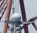
They likely thought horizon search is not very good due to the height of the arrays from the sea level. SPY-1D should have a similar problem. However, this is mitigated by having secondary search radars on the mast. In this case, the Type 364 radar on top of the mast in white round radome.

View attachment 51281

View attachment 51282

The USN solution is this:
Please, Log in or Register to view URLs content!

Why don't the Chinese design the control tower taller on all their warships to improve horizon search?
 

Tam

Brigadier
Registered Member
Yes, a wide ratio radar is of course capable of elevation scan. But that doesn't say much about its search beam width. I will explain why I think that is important.

The Wikipedia article claims that the narrow C-band arrays are used for HQ-9 guidance. Given that back then the missile guidance was either TVM or SARH, those bars would then also have to serve as illuminators - in addition to any other function they might have. We've seen a photograph that does give some credibility to the claim.
images-1-jpeg.51290

A thought experiment. I will assume the bar array operates in the middle of C-band, therefore at a wavelength (lambda) of about 5cm. I will also assume a generous EFOV of +/-60 degrees, which can be achieved by module spacing of 0.536 lambda, but let's take 0.5 lambda, i.e 2.5cm. According to the article, the array height is 20cm. That would let us pack 8 or 9 modules along vertical axis. I don't have a formula at hand to compute the vertical beam width, but according to illustrations here:
Please, Log in or Register to view URLs content!

the beam width would be at least 10 degrees wide (in vertical axis) and the antenna gain would suffer accordingly. Horizontally, the beam can be made very narrow. Therefore, the illumination beam would resemble a fan. For a long range illuminator, you would not want to waste all that energy, not to mention increase the risk of multiple echos.

But first, if the C-band is specifically used an FCR, its a stronger bet that the elements will be on the shorter side of the spectrum. That would be 3.75 cm, and the key dimension length of the C-band element would be 1.87 cm. On a 20cm array, that's going to be like 10 to 11 elements.

The problem of the Wiki entry is that you also have this bit of information posted as the specs for the Type 346, production version.

For Type 346:
Please, Log in or Register to view URLs content!


  • Total number of faces: 4
  • Bands: S and C
  • S-band array size & shape: octagon with 4 meter diameter
  • C-band array size & shape: ≈ 0.8 to 1 square meter rectangular ea.
  • Number of S-band arrays: 4 (1 per face)
  • Number of C-band arrays: 8 (2 per face)
  • Maximum search range (km): > 450
  • Weight (t): < 16 above deck
  • Scan: 120°
  • Elevation: 0° to 90°
  • Cooling: Air (Type 346), Liquid (Type 346A)
The description here does not match this text:

"This main S-band array is sandwiched between two rows of C-band arrays, each with size of 0.2 meter by four meter.
Please, Log in or Register to view URLs content!
The two C-band arrays are used to control HHQ-9 SAMs. "

Second, the C-band array is 0.8 to 1 square meter rectangular

The lower entry isn't just different from the other entry, it also seems more correct.

IMO the Wiki entry is pointing to the right direction, but machine translation, poor knowledge of English construction,

This line is also interesting.

"The very first prototype of the series Type 115 layout similar to that of AN/APQ-53 radar of
Please, Log in or Register to view URLs content!
that includes two arrays:
Please, Log in or Register to view URLs content!
"

I think this is more in reference to the prototype HT-233 array with the two arrays on the bottom.

HT-233-Engagement-Radar-4S.jpg


With the production version looking like this.

images (6).jpeg

Note the arrays on the bottom. Also I think these small arrays are about 1/4th the width of the main array on the final version, 1/5th in the prototype version. Between the original and final version, they increased the size of the targeting arrays.

If the Wiki article was wrong on this, it could very well be wrong on other details as well. An alternate explanation is that those bars serve as IFF. But then, weren't the bar shaped arrays above the bridge suspected to serve the IFF role?

Its possible. This is also in line with my suspicion that the top bar is an IFF. Look again at the final version HT-233 radar, and the bars on top is IFF.

However, all these does not make CMANO's entry anymore correct. The CMANO's entry lists the radar to have a range of over 325km, which for a C-band radar is quite impressive. If you have a phase array with a 350km range at S-band, and another phase array at 325km range at C-band, the latter, would simply be of course, better. The only point in having a longer frequency is the advantage of range. In terms of tracking, its X > C > S.

But do note from the Wiki entry, the C-band Institute 23 entry is only 120km, and that closely matches the marketing information with regards to the slant range of the HQ-9, which is about 120km or 125km. The C-band elements would have been an early type, and I don't expect the generation level of the technology to be that advanced. The 325km or so with a C-band would have implied a strong generation advancement, and saying that this is an early 1990s technology would be a strong and blatant contradiction. I find it more plausible to believe that 350km ranges are achieved with an S-band rather than a C-band.

As for this, i am starting to think that this is NOT Type 346 but 346A. The reason for this being the panel is square to square.

images (1) (1).jpeg

I won't call the small tiny bars on top of the bottom either IFF or illumination arrays --- the IFF is located outside of the main panel on top of the bridge. These small bars might be instead, side lobe cancelers.
 

Tam

Brigadier
Registered Member
Why don't the Chinese design the control tower taller on all their warships to improve horizon search?

The Chinese does not have a horizon search problem. Never had. Everyone focuses on the fancy main radar and never looks at the secondary radars.

download (4).jpeg 199px-Type_364_radar.jpg


This is called the Type 364 radar or known by its export as SR64C. This is a C-band radar. It sits on top of the mast of every large PLAN ship --- 052B, 051B refit, 051C, 052C, 052D,054, 054A, Sov refit, 052 refit, 056. The Liaoning and Carrier 002 might also have two of these, one in each side of the island. Its topmost position gives it max horizon reach, and C-band allows it to differentiate objects closer to the water or at the water better than S-band. The fact that it is in almost every PLAN ship is a testimony that this device works. I say almost because there is one important warship that does not have it --- the Type 055 --- and its because something else has replaced it.

It is responsible for queuing the HQ-10 missile launcher and the Type 730/1130 CIWS.

On the 054A, its the radar on top of the funnel. Its not as if the Type 382 on the main mast cannot handle horizon scan, which it does and most certainly does well, but i kind of notice the Chinese Navy likes having insurance policies on their designs.

DSC07380.JPG
 

Max Demian

Junior Member
Registered Member
As for this, i am starting to think that this is NOT Type 346 but 346A. The reason for this being the panel is square to square.

View attachment 51331

I won't call the small tiny bars on top of the bottom either IFF or illumination arrays --- the IFF is located outside of the main panel on top of the bridge. These small bars might be instead, side lobe cancelers.

This photo emerged during the restart of the 052C construction. The four holes in the corners were rumored to be for air cooling purposes. To me the geometry looks taller than wider, fitting the 052C face.

Even if we assume the bars to be 25 cm tall by 4m wide to give 1m2 per article, and the lowest allowed lambda for C band (the upper bound for X band), that still gives only 14 elements in the vertical axis. The beam would still be far too wide in vertical axis for illumination.

For comparison, the APAR has about 60 elements in X and Y and probably has to use the entire array when illuminating to get something close to a 2 degree beam. The SPY-1 has just shy of 70 in X and Y for a beam width of 1.7 degrees. No wonder they went with 2.3m diameter parrabollic X-band antennas for their long range illuminators.

The question then remains what's guiding the HQ-9A to target? Either it had active guidance even back then, or the Type 346 is also the illuminator. But as I explained above, it is difficult to reconcile that with the information from the Wiki article. If we are to believe published sources, then the entire array would be in C-band, which together with ICWI would allow it to both search and illuminate with narrow beams in a time sharing manner.

Tam, you're looking at the wrong entry for Type 346 in cmano db. The one on Type 052C is modelled to have a range of 278km. This handbook comes with useful figures to compare 2-way radar attenuation across different radiation bands:
Please, Log in or Register to view URLs content!
 

Tam

Brigadier
Registered Member
This photo emerged during the restart of the 052C construction. The four holes in the corners were rumored to be for air cooling purposes. To me the geometry looks taller than wider, fitting the 052C face.

The restart of the 052C construction overlaps with the beginning of 052D construction, with the Kunming at 2012.

It looks straight square to me. Given the angle viewed and the radar itself has a slant, it needs to look more rectangular if it was the Type 346.

t4EKkbt.jpg

Even if we assume the bars to be 25 cm tall by 4m wide to give 1m2 per article, and the lowest allowed lambda for C band (the upper bound for X band), that still gives only 14 elements in the vertical axis. The beam would still be far too wide in vertical axis for illumination.

Per article? The article also said *rectangular*. You are assuming its a straight 4 meter bar. The pictures of the HT-233 implementation showed rectangles, not bars. I am pointing out that the Type 346 illumination arrays may actually be much more like the HT-233's or MPQ-53's.

The number of the elements along the horizontal is what is used to control the width of the beam and how wide the angle of its horizontal sweep.

Vertical number of elements determines how far the vertical sweep angle of the beams. The more elements in a given area, the greater the angle.

The 4 meter bar does not produce a 4 meter wide beam. You can set for example, a matrix of 14 elements vertical with an X number of elements in the horizontal, for one beam, dividing the bar into smaller rectangles.

For comparison, the APAR has about 60 elements in X and Y and probably has to use the entire array when illuminating to get something close to a 2 degree beam. The SPY-1 has just shy of 70 in X and Y for a beam width of 1.7 degrees. No wonder they went with 2.3m diameter parrabollic X-band antennas for their long range illuminators.

APAR won't use its entire array for illumination. It would have to divide its array face for multiple beams simultaneously, some to search for targets, some to track existing targets, others to illuminate to engage.

The question then remains what's guiding the HQ-9A to target? Either it had active guidance even back then, or the Type 346 is also the illuminator. But as I explained above, it is difficult to reconcile that with the information from the Wiki article. If we are to believe published sources, then the entire array would be in C-band, which together with ICWI would allow it to both search and illuminate with narrow beams in a time sharing manner.

Its hard to reconcile the range given for the Type 346 or 346A to be C-band.

Tam, you're looking at the wrong entry for Type 346 in cmano db. The one on Type 052C is modelled to have a range of 278km. This handbook comes with useful figures to compare 2-way radar attenuation across different radiation bands:
Please, Log in or Register to view URLs content!

Even then 278 km is a lot for a C-band radar. Patriot MPQ-53 is instrumented only to 170 km. EMPAR is only 150km.

Please, Log in or Register to view URLs content!


Please, Log in or Register to view URLs content!


HT-233 is only 120km.

Please, Log in or Register to view URLs content!


CMANO has HT-233 at 166 km.

Please, Log in or Register to view URLs content!


MPQ-65 is only 100km.

Please, Log in or Register to view URLs content!


CMANO has the PAC 3 radar range at 166km.

Please, Log in or Register to view URLs content!


Do you see a picture emerging here?

And this?

Please, Log in or Register to view URLs content!


Flap Lid and the S-300 missiles uses FMCW, not ICW.
 
Last edited:

Tam

Brigadier
Registered Member
This photo emerged during the restart of the 052C construction. The four holes in the corners were rumored to be for air cooling purposes. To me the geometry looks taller than wider, fitting the 052C face.

Even if we assume the bars to be 25 cm tall by 4m wide to give 1m2 per article, and the lowest allowed lambda for C band (the upper bound for X band), that still gives only 14 elements in the vertical axis. The beam would still be far too wide in vertical axis for illumination.

For comparison, the APAR has about 60 elements in X and Y and probably has to use the entire array when illuminating to get something close to a 2 degree beam. The SPY-1 has just shy of 70 in X and Y for a beam width of 1.7 degrees. No wonder they went with 2.3m diameter parrabollic X-band antennas for their long range illuminators.

I am not clear what you are saying. If Thales APAR requires its entire array to steer a single beam, it won't be able to use the same array face to multitask, search and track for multiple targets, that its sale literature vaunts it to be. Each face should have steer no more than 60 degrees angle, but then that's why you have four faces in four directions.

The problem of phase arrays is the limit you can steer the beam angle off broadside, the phase array loses db the more the beam angles, no more greater than 60 degrees. Over that the lobes begin to grate.

1/2 of wavelength between one element to another allows for a beam that angles up to 45 degrees.

Going with a mechanical illuminator (SPG-62) is because you can steer the beam to any angle desirable, limited only to the antenna's gimballing mechanism. However, parabolics produce all these sidelobes that are not just wasted energy, but makes the antenna detectable by threat ESM.

Type 346 should also be about a little more 70 x 70 for over 5,000 T/Rs for S-band. That would have put it on the same boat as SPY-1. It simply does not have anything that can be used a mechanical illuminator. Think about that.

If Type 346 is about 4 meter size and C-band, that could mean closer to 10,000 T/Rs, or a 100 x 100 element array. MPQ-53, at 2.53 meters, has about 5,000 elements, and about 70+ x 70+ element array. If you can do nine targets for a 70 x 70 element, that maybe around 23 x 23 elements minimum per target is being dedicated. Compared to the MPQ-53, if the Type 346 is a C-band, 4 meters, should have 10,000 elements on a 100 x 100 plus element array, and nearly 300 km range, It may be able to target as much as 18 per face. If your C-band can reach nearly 300km, so can your SARH missile in theory if it has enoughj propellant and flight range.

Mind blown. The system is superior to AEGIS in every way with large margins. That I find hard to believe. A Type 052C or D would have 40,000 elements in a single ship, double of that of a Burke. The S-band radar + ARH missile seems much more elegant to explain. S-band for Type 346 makes a better fit given that the Type 364 (SR64) radar on top of the mast is already on C-band.

200452714545719 (2).jpg
 
Last edited:

Max Demian

Junior Member
Registered Member
Tam, let's not dwell on the cmano db. It's just one of several sources out there. But let me say this : the per-platform data that you see in the online browser is just a small subset of the actual in-game data. They use a rather elaborate EM propagation model(for a game). If you're curious, check out the excel sheets in this thread:
Please, Log in or Register to view URLs content!


As for the radar panel photo, you might have a point there!
But be that as it may, my speculation is about the Type 346, not Type 346A. If the latter is 4m wide, then the former is clearly narrower. If you have some data/measurements on the Type 346 face dimensions please share.

As I said before, I have reservations with the veracity of the data in the Wiki article. In particular with the claim that the the FCR comes in form of 2 rectangular arrays of dimensions 4m by 0.2m:
"
The original Star of the Sea design consisted of two active arrays: an octagon S-band array with diameter of four meters for search and track, and a much smaller C-band active array with diameter of 60 centimeters for missile control. With an area approximately 0.3 square meter, the small C-band array could not effectively control the HHQ-9 SAM with the increased range and reduced tracking signal. A larger C-band array was needed. The 14th Institute design team abolished the small C-band array, and adopted two larger 0.2 meter by four meter rectangular arrays, and in terms of area, each C-band array is more than two and half time of the original small array with diameter of 0.6 meter. "

What I find interesting is that on several places in the article there is mention of a tracking signal being handled by C-band arrays.
"
Two of the major changes are the weakening of HHQ-9 tracking signal and the tracking range of HHQ-9 respectively. For the signal tracking, the signal is greatly reduced ostensively to reduce the probability of being intercepted by enemy. For the tracking range increase, it was ostensively due to the range of HHQ-9 has being increased by several dozen kilometers, so tracking range must be increased accordingly."

This sounds to me like 2-way communication between the missile and Type 346 C-band arrays. I could interpret this as a component of inflight midcourse guidance. For reasons that I explained above, this makes much more sense than these arrays serving as illuminators.

But I see that you are drawing a similar conclusion. I trust that you understood the point of my thought exercise.

As for your remark about the relation of array size and number of elements per axis, the pencil beamwidth (think of width as diameter per axis) is related to antenna gain. You can find a nice discussion with some formulas here:
Please, Log in or Register to view URLs content!
 
Last edited:
Top