055 DDG Large Destroyer Thread

Status
Not open for further replies.

Tam

Brigadier
Registered Member
In this case, it is the rumours chronicling the development of 346 from a few years back which stated that the arrays sandwiching the main central array are C band AESAs.

They were not stated as IFF arrays.

That's because the people transmitting the rumors may not be familiar with RF tech. You will have a hard time finding any missile guidance illuminator that is stripe shaped anywhere around the world. There are times when a round peg isn't going to fit into a square hole, and you have to call it out.

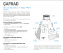
This is the model for the future Turkish destroyer. Like the Type 055 it has radars embedded in the deckhouse, not just one but two sets. Note it has missile target illuminators which is the one marked as AYR Sistemi. It is not shaped like a stripe. The array has to steer its beam up and down as much as left and right. For this reason, the array has to be symmetrical with an equal number of elements for the elevation as it is for the horizontal. Another thing is that arrays have to be much larger for it to have a sufficient number of elements to attain the needed level of transmission power.

Note that it also has an X-band radar on the top mast, just like the 055. But the CFR Sistemi is not used for missile guidance but is used for air and surface detection of sea skimmers at the edge of the radar horizon. The position of this radar gives it the height it needs for an extended radar horizon. My belief is that the X-band radars on the 055 is used the same way.

Please, Log in or Register to view URLs content!


Video-Turkish-AESA-Radar-ÇAFRAD-Completes-First-Live-Fire-Test.jpg

Screenshot 2020-02-10 at 11.47.32 AM - Edited.png
 
Last edited:

Blitzo

Lieutenant General
Staff member
Super Moderator
Registered Member
That's because the people transmitting the rumors may not be familiar with RF tech. You will have a hard time finding any missile guidance illuminator that is stripe shaped anywhere around the world. There are times when a round peg isn't going to fit into a square hole, and you have to call it out.

This is plans for the future Turkish destroyer. Note it has missile target illuminators. It is not shaped like a stripe. The array has to steer its beam up and down as much as left and right. For this reason, the array has to be symmetrical with an equal number of elements for the elevation as it is for the horizontal.

View attachment 57403

... I'm surprised that you're not aware of what I'm talking about.

Back in 2016 there was a rather detailed post about the 346's development from someone who was part of the development process. It was discussed on the various PLA watching forums very throughly at the time. While all of the details could not be verified, it was generally accepted that the design of the 346 and the C band component in particular was likely valid and would explain the arrangement of the Type 346's array beneath its cover.
The original post text was copied over to CDF, which you can access here:
Please, Log in or Register to view URLs content!


A very through English translation of the 346's development is actually on the Wikipedia page of Type 346 of all places
Please, Log in or Register to view URLs content!
 

Tam

Brigadier
Registered Member
... I'm surprised that you're not aware of what I'm talking about.

Back in 2016 there was a rather detailed post about the 346's development from someone who was part of the development process. It was discussed on the various PLA watching forums very throughly at the time. While all of the details could not be verified, it was generally accepted that the design of the 346 and the C band component in particular was likely valid and would explain the arrangement of the Type 346's array beneath its cover.
The original post text was copied over to CDF, which you can access here:
Please, Log in or Register to view URLs content!


A very through English translation of the 346's development is actually on the Wikipedia page of Type 346 of all places
Please, Log in or Register to view URLs content!

I am very aware of that actually. But it still is, a square peg trying to fit a round hole. It doesn't fit no matter how you slice it.

They are trying to fit pieces that don't fit in the first place.

HQ-9 uses C-band as for missile guidance and illumination based on the land model.

But they have no idea that HT-233 uses its entire face for that purpose. The HT-233 doesn't use strip like illuminators. The whole radar you see also acts as the missile illuminator itself.

HQ-9-HT-233-Engagement-Radar-1S.jpg

The idea isn't new. Its a copy of the Flap Lid and Tombstone radars used with the S-300 missile complex. The whole array you see here acts as the missile illuminator. Unlike dedicated SPG-62 illuminators like you see on the AEGIS system, these are complete radars because they can detect, range and track targets prior to switching to an engagement and target illumination mode, like aircraft fighter radars. The main difference between S-300 Flap Lid and Tombstone vs. HT233 and HQ-9 is that the S-300 system uses X-band instead of C-band, therefore requiring a much finer and denser array face in terms of element count, at least over 10,000 elements, given the array size. The use of C-band suggests a connection to the Patriot system which uses C-band, and note also as well, the MPQ-53 radar used for the Patriot also uses its entire face for missile guidance illumination.

This leads to only three conclusions with the Type 346 array on the 052C:

1. It uses S-band for missile illumination. This actually has been experimented with AEGIS before but never went through. S-band isn't the most ideal for it.
2. The entire array is in C-band. This however means a very high element count given the array size, as C-band requires a denser element face than S-band. Very expensive in terms of cost.
3. That the missiles are completely command guided with ARH guidance at terminal stage, all from the first place right at the very beginning, which means no missile illumination from the ship whatsover.


S-300PMU2-Favorit-30N6E2-Tomb-Stone-VPVO-Deployed-3S.jpg
 

Iron Man

Major
Registered Member
It means in the case of the thinner ones, the LNA itself is not on the array but somewhere in the bottom of the array right underneath the roof of the deckhouse. In the case of the IFF arrays on the 055, the LNAs. is right behind the array itself
This is pure speculation on your part and I'm pretty sure we both know that.

Oh wait. You do realize that the PESAs and AESAs you shown are not phase arrays, right? .How can a PESA and an AESA not be a phase array?

That's because PESA and AESA only stands for Electronically Steering Arrays. Not all ESAs are phase arrays. There are other ways that arrays can electronically steer. There is no phase shifters used here. That's why they look thin, they comprise of a planar array with linear elements.

And that is why it looks like this. And not like this.

The one on the left is a true phase array. The one on the right is not a phase array. Both are PESAs however.

I am referring to AESAs that are planar arrays that scan only in elevation. The way they do it is that every linear element has a slight delay in the feed that causes a slight change in the emitter frequency of each linear element. This results in a phenomena called frequency steer. These arrays scan and steer up and down this way by frequency change, but has no ability to steer right and left, which is why they have to be mechanically rotated.

So you have arrays with only linear elements but without phase shifters.

But this is still an AESA because when you look at it, note the how the center of it is thick. That's where the modules that support each linear element are housed. In this array, you can see through it just like the one on top, and you can see its back.

This is another frequency steering array, like the array on top, it is not a phase array per but it is still a PESA

Unlike TPS-59 which has the modules on the center of the array, SPS-48 does not have any modules on the back of the array. You can also see that SPS-48 also has a serpentine line feed on the side that feeds every linear element with a sequential slight delay, causing a slight change in each frequency emitted on each linear element. The frequency change causes the radiating pattern to steer up and down. If you go back to the second picture of this post, you can see the radar on the right of the Tombstone phase array also has its line feed on the side of the array. These arrays only scan by elevation by frequency steering and has to be mechanically rotated for horizontal scanning.

In the case of the AESA doing frequency steer, each module feeding each linear element uses a time delay from one another in a sequential manner.

That's why to tell a PESA from an AESA, you have to see what's in the side and back. And quite frankly, even YLC-2 and TPS-59 still looks thicker than SPS-48 because of the large and thick center backbone of the radar that houses all the modules.
Let's not get bogged down with the introduction of yet another red herring. YOU were the one who tried to distinguish between PESA and AESA on top of the 052D and 055 without specifying whether you claimed they were elevation+azimuth-scanning arrays vs elevation scanning-only arrays, which regardless in the end makes no real impact either way on distinguishing their ultimate use whether in the form of an IFF array or a radar array or some other function altogether. The thin Cyient AESA that I posted scans in both azimuth and elevation based on their literature description and happens to be thinner than all the PESAs you posted, which your theories seem not to be able to account for. And to be perfectly honest, in the context of a military-related discussion, "phased array" and "ESA" are pretty much invariably used interchangeably.

Finally, there is one thing all these radars have in common is that all have IFF transponders at the top of the radar. The most common position for IFF is to be directly at the top of the radar, and that is why the bars on the top of the Type 346B on the 055 should be IFF. The next common position would be at the bottom of the radar like on the Tombstone there. There are exceptions to this like when you have ring shaped IFF however.
Is there some logical reason you can think of where an IFF array HAS to be positioned directly on top of a radar array, or facing the same quadrant? Because I can't think of one. The mobile truck-mounted type of arrays have obvious logical reasons for this kind of co-location but ship-mounted arrays especially on larger ships don't need to, so there is no compelling case to be made for the bar array on top of the 055 to have to be an IFF array just because it's on top of the 346. In fact the port and starboard IFF arrays of CV-16 are located all the way at the forward end of the island while the 346 arrays are located all the way at the rear end of the island. Co-location of the IFF array and the main radar array on a ship is clearly not mandatory.
 

Blitzo

Lieutenant General
Staff member
Super Moderator
Registered Member
I am very aware of that actually. But it still is, a square peg trying to fit a round hole. It doesn't fit no matter how you slice it.

They are trying to fit pieces that don't fit in the first place.

HQ-9 uses C-band as for missile guidance and illumination based on the land model.

But they have no idea that HT-233 uses its entire face for that purpose. The HT-233 doesn't use strip like illuminators. The whole radar you see also acts as the missile illuminator itself.

View attachment 57405

The idea isn't new. Its a copy of the Flap Lid and Tombstone radars used with the S-300 missile complex. The whole array you see here acts as the missile illuminator. Unlike dedicated SPG-62 illuminators like you see on the AEGIS system, these are complete radars because they can detect, range and track targets prior to switching to an engagement and target illumination mode, like aircraft fighter radars. The main difference between S-300 Flap Lid and Tombstone vs. HT233 and HQ-9 is that the S-300 system uses X-band instead of C-band, therefore requiring a much finer and denser array face in terms of element count, at least over 10,000 elements, given the array size. The use of C-band suggests a connection to the Patriot system which uses C-band, and note also as well, the MPQ-53 radar used for the Patriot also uses its entire face for missile guidance illumination.

This leads to only three conclusions with the Type 346 array on the 052C:

1. It uses S-band for missile illumination. This actually has been experimented with AEGIS before but never went through. S-band isn't the most ideal for it.
2. The entire array is in C-band. This however means a very high element count given the array size, as C-band requires a denser element face than S-band. Very expensive in terms of cost.
3. That the missiles are ARH guided from the first place right at the very beginning, which means no missile illumination from the ship whatsover.


View attachment 57406


As far as speculating what kind of arrangement the Type 346 has, prior to the release of that post I think that the variety of speculation around it were mostly all equally valid.

But afterwards I'm not sure how one can seriously claim that it operates differently to how the post describes, considering there is nothing particularly impossible or difficult to imagine about it.
Basically all of your possibilities are mentioned or alluded to in the development of the radar -- e.g.: that the original PLAN requirement was for a full C band radar, and that 14th institute had considered a separate S band and C band radar with two distinct separate arrays.
It was through a variety of processes that they eventually settled on that the S band + C band design.
 

Tam

Brigadier
Registered Member
This is pure speculation on your part and I'm pretty sure we both know that.

Did I already pointed out that Henri K. asked a French navy officer whose speciality is in EW and asked what the parts where? He pointed out that the arrays on top of the main Type 346 radars were IFF.


Let's not get bogged down with the introduction of yet another red herring. YOU were the one who tried to distinguish between PESA and AESA on top of the 052D and 055 without specifying whether you claimed they were elevation+azimuth-scanning arrays vs elevation scanning-only arrays, which regardless in the end makes no real impact either way on distinguishing their ultimate use whether in the form of an IFF array or a radar array or some other function altogether. The thin Cyient AESA that I posted scans in both azimuth and elevation based on their literature description and happens to be thinner than all the PESAs you posted, which your theories seem not to be able to account for. And to be perfectly honest, in the context of a military-related discussion, "phased array" and "ESA" are pretty much invariably used interchangeably.

I also told you there are not radars, and they don't scan. If you are using phase arrays, the arrays form beams to the tracked aircraft, and signaling them with a coded message using a sequence of transponder pulses. Since this is communication, you don't need the signal to be reflected back, it only needs to be strong enough for a one way trip.

Cyient does not make radars, only the modules. You should know better than that when companies use stock photos to embellish their sales literature.

In terms of military application there is a difference between phase array and planar arrays. Frequency scanning planar arrays are in no exception, used for aerial surveillance, and they have a distinct working signature from an EW point of view. True phase arrays on the other hand, also have a distinct working signature, and point to the presence of a fire control radar. They are the ones that are going to lock on to you for a firing solution.

Is there some logical reason you can think of where an IFF array HAS to be positioned directly on top of a radar array, or facing the same quadrant? Because I can't think of one. The mobile truck-mounted type of arrays have obvious logical reasons for this kind of co-location but ship-mounted arrays especially on larger ships don't need to, so there is no compelling case to be made for the bar array on top of the 055 to have to be an IFF array just because it's on top of the 346. In fact the port and starboard IFF arrays of CV-16 are located all the way at the forward end of the island while the 346 arrays are located all the way at the rear end of the island. Co-location of the IFF array and the main radar array on a ship is clearly not mandatory.

You don't think I know about CV16? Even in this case, the IFF arrays are still facing the same quadrant as the Type 346 radars. You have to remember this ship is not designed from the ground up for the PLAN's sensor configuration, and rather they have to design around it. It is possible there is no room to put the supporting circuitry for the IFF to be on top of every array. But on CV17 Shandong, which is purposedly built around PLAN's sensor configurations, you achieve a much more optimal design.

The thing about linear and planar arrays is that transmit signal and echo receive signal loss increases as you go off center from the broadside of the array. If the radar is pointing to this direction, your linear IFF should be pointing in this direction and not that direction. While it is not mandatory to be on the same facing quadrant, it is certainly not optimal to be on a quadrant facing a different direction, and you certainly desire the optimum, and you should pick the optimum when it presents itself.

The best case when IFF is not on top of a radar (even F-16s have IFF blades on the nose) is the use of ring type IFF. You see this in Arleigh Burke and Italian FREMM. It is possible, and I am speculating at this point, there is additional and secondary ring type IFF on the 052D on top where the Type 364 radar is. The smaller IFF allows the Type 364 to interrogate incoming targets far into the edge of the radar horizon before they come into the radar horizon of the lower placed IFF on top of the Type 346 radars or within. The ring type IFF on the ABs and Italian FREMM are also set high for this reason.

There is another possibility that I have not mentioned yet, but is entertaining, and that is all eight bars on top of the 055 are IFF, and might also dual purpose as additional surface scanning radars. The larger bars on top of the 346B serve as IFF for these, and the smaller bars next to them serve as IFF for the X-band radar on the mast, as they have same direction as the X-band radar. This is especially if the X-band radar is also being used as a surface scanner, and allows the X-band to interrogate objects within its quadrant.
 
Last edited:

Tam

Brigadier
Registered Member
As far as speculating what kind of arrangement the Type 346 has, prior to the release of that post I think that the variety of speculation around it were mostly all equally valid.

But afterwards I'm not sure how one can seriously claim that it operates differently to how the post describes, considering there is nothing particularly impossible or difficult to imagine about it.
Basically all of your possibilities are mentioned or alluded to in the development of the radar -- e.g.: that the original PLAN requirement was for a full C band radar, and that 14th institute had considered a separate S band and C band radar with two distinct separate arrays.
It was through a variety of processes that they eventually settled on that the S band + C band design.

Doing a dual band AESA circa 2003 for a country that hasn't had much of a history in doing AESA before that, as did most other nations during that time, would have been an astounding technical feat. This is in addition to having a high powered emission source so close to the main radar and within the same radome, and achieve this without significant interference. Never mind such a high powered beam to sufficiently illuminate targets over 100km from such a thin strip array would have required extremely powerfully dense elements at a time no one is using Gallium Nitride yet.


Just let this sink in. This is what 2018 SPY-6 with DBR (Dual Band Radar) looks like by Raytheon. The other band, the X-band, is the radar on top of the structure. The smallish radar, which is a SPQ-9B, isn't used for missile target illumination and still requires SPG-62 for that purpose. It doesn't use small strips of arrays tor target illumination. The SPQ-9B is set on top of the mast, and is used as a surface spotter.


unnamed.jpg 38c6188b55da9faf5e90c0cf49280315.jpg
 

Blitzo

Lieutenant General
Staff member
Super Moderator
Registered Member
Doing a dual band AESA circa 2003 for a country that hasn't had much of a history in doing AESA before that, as did most other nations during that time, would have been an astounding technical feat. This is in addition to having a high powered emission source so close to the main radar and within the same radome, and achieve this without significant interference. Never mind such a high powered beam to sufficiently illuminate targets over 100km from such a thin strip array would have required extremely powerfully dense elements at a time no one is using Gallium Nitride yet.


Just let this sink in. This is what 2018 SPY-6 with DBR (Dual Band Radar) looks like by Raytheon. The other band, the X-band, is the radar on top of the structure. The smallish radar, which is a SPQ-9B, isn't used for missile target illumination and still requires SPG-62 for that purpose. It doesn't use small strips of arrays tor target illumination. The SPQ-9B is set on top of the mast, and is used as a surface spotter.


View attachment 57409 View attachment 57410

It is an impressive feat, but just because a radar is "dual band" doesn't mean all dual band radars are equal.
For example, the C band radar on 346 are not the same kind of MFRs that you would expect the 055's different S and X band radars to be capable of, but rather it is more oriented for guiding the ship's missiles instead.

The use of dual radar sets to try and achieve a mission capability is not unique either, for example the original SCANFAR radars could be argued to be one of the earliest "dual band radar" types in the world as we know it today.
Australia's CEAFAR and CEAMOUNT radars that they have refitted onto their ANZAC frigates is also S and X band and they weren't exactly known for producing AESAs before that either.

So no, I don't think that just because the 346 has an S band and C band component means it is inherently much more difficult to develop merely by the virtue of being dual band. The role of the C band component in particular is quite limited.


As for the 346 itself, I don't consider the topic of its array arrangement to be something that is up for serious debate (and I didn't think it would be for the last 3+ years since that post). I believe that until such a time where new information comes to light to make us seriously doubt the statements from that particular post, then the consensus is that the 346 has a central S band array sandwiched by two C band arrays.
 

Tam

Brigadier
Registered Member
It is an impressive feat, but just because a radar is "dual band" doesn't mean all dual band radars are equal.
For example, the C band radar on 346 are not the same kind of MFRs that you would expect the 055's different S and X band radars to be capable of, but rather it is more oriented for guiding the ship's missiles instead.

The use of dual radar sets to try and achieve a mission capability is not unique either, for example the original SCANFAR radars could be argued to be one of the earliest "dual band radar" types in the world as we know it today.
Australia's CEAFAR and CEAMOUNT radars that they have refitted onto their ANZAC frigates is also S and X band and they weren't exactly known for producing AESAs before that either.

So no, I don't think that just because the 346 has an S band and C band component means it is inherently much more difficult to develop merely by the virtue of being dual band. The role of the C band component in particular is quite limited.


As for the 346 itself, I don't consider the topic of its array arrangement to be something that is up for serious debate (and I didn't think it would be for the last 3+ years since that post). I believe that until such a time where new information comes to light to make us seriously doubt the statements from that particular post, then the consensus is that the 346 has a central S band array sandwiched by two C band arrays.

CEAFAR and CEAMOUNT are not sandwiched arrays. Countries that don't have a prodigious history of making AESAs, including Australia, Israel and Turkey are not trying very cutting edge attempts on their AESAs either, in fact, they are quite conservative.

After many years since the first Type 346 was introduced, which is more than a decade ago, not one, not a single array, even among the most experienced designers and manufactures like Raytheon and Thales, ever came out with a sandwiched array configuration, nada, zero. Even after all the years and experience accumulated since then. The other problem to that, is that there is no logic to it.
 

Blitzo

Lieutenant General
Staff member
Super Moderator
Registered Member
CEAFAR and CEAMOUNT are not sandwiched arrays. Countries that don't have a prodigious history of making AESAs, including Australia, Israel and Turkey are not trying very cutting edge attempts on their AESAs either, in fact, they are quite conservative.

After many years since the first Type 346 was introduced, which is more than a decade ago, not one, not a single array, even among the most experienced designers and manufactures like Raytheon and Thales, ever came out with a sandwiched array configuration, nada, zero. Even after all the years and experience accumulated since then. The other problem to that, is that there is no logic to it.

I think that is the wrong way to approach it.

The first question should be -- do we consider the relevant details of a post/rumour to be credible?
The second question should be -- does what we physically see correspond to the relevant details of a post/rumour?

And third and lastly -- is suggestion of a post/rumour technically possible?

For question one, I consider the answer to be yes. Specifically I don't think there is any reason to within the post itself to doubt the assertions of a dual C band array sandwiching the main S band array
For question two, I also consider the answer to be yes. We know what the array configuration of the Type 346 looks like underneath its cover and it is exactly as the post describes it.
For question three, I also consider the answer to be yes as well. The fact that other radars have not adopted such an arrangement does not mean it is technically impossible, it could just mean that there were better solutions and the type 346 ended up with its configuration to suit their own requirements at the time.
There is a difference between "this is a strange way of doing things" versus "this is a configuration which is technically impossible".
 
Status
Not open for further replies.
Top