Naval missile guidance thread - SAM systems

Brumby

Major
Let me summarize what I've learned from the exchange we've had in the last week or so, as it relates to the difference between PESA/AESA, and how AESA radars in general are constructed.

An AESA radar can have just one transmitter, just like a PESA radar. The key difference is, that the high power amplifiers (HPA) are distributed throughout the antenna in an AESA architecture. Whereas, in a PESA radar, the HPA are not part of the antenna. Similarly, on the receive side the low noise amplifier (LNA) is distributed across the antenna in an AESA architecture. Whereas, in a PESA radar, there is one LNA that receives the signal input from the beamformer, typically per sub-array. Apparently, some modern PESA radars introduce separate receive channels with the LNAs inbuilt into the array, just like an AESA radar, equaling their advantages on the receive side. Examples proposed: Russian Bars/Irbis radar, American SPY-1 radar.

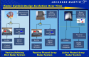
On both the transmit and receive side, AESA radars, just like PESA, started off using analog wavefront generation and analog beamforming. Ever since, there has been a steady trend towards going more digital and ever closer to the antenna, with the end goal being a digital array radar (DAR). Even though this trend appears to be associated primarily with AESA radars, I think it is to a large degree orthogonal to whether a radar is PESA or AESA. I say this, because there are exist partial implementations of the concept, such as digital beamforming on the receive side that both PESA and AESA can perform. Ditto for WFG. However, a true DAR does require HPAs to be part of the antenna, so AESA is the only right architecture to achieve this.

Some misconceptions that have been shown false, are:
- PESA must have one transmitter
- AESA has as many transmitters as there are TRMs.
Both systems can have just one transmitter. There are PESA that have 8 or more transmitters: SPY-1 and Cobra Dane to name the examples mentioned in the discussion here.

"Multiple beams": it is commonly advertised that a big advantage of AESA is forming multiple transmit beams. However, what seems to be overlooked or misunderstood, is that both PESA and AESA can and routinely do form multiple receive beams. From what I could gather, the common practice appears to be to send out one beam on transmit and then decompose it into smaller beams on the receive side, through either analog or digital beamforming. On my todo list is to understand how digital beamforming on the transmit side works. Would appreciate if someone can offer pointers.

In my opinion most of your conclusions are wrong because they are grounded on disparate pieces of radar technology rather than on the end product and how they actually operate.

For example, who the heck would build a functioning AESA radar based on a single TR? Just give me one example of such a moron and I promise I will not comment further.

AESA radar by design are superior to PESA on many fronts including on sensitivity. This is a well established fact from technical literature. I simply don't understand why it became such a long drawn argument over a well established fact. I can give you two sources

(1)
1583796045864.png
1583796081491.png
(2)

1583796126439.png)
 
  • Like
Reactions: Tam

Tam

Brigadier
Registered Member
Yes, it is possible to a turnable AESA .

I think you see the inflexibility, slow rotation and limited area of this kind of geometry : )

The examples I have shown you --- AESA radars for the Eurofighter, FC-1, Saab Gripen --- are intended to replace earlier slotted planar array on these fighters. Replacement AESA radars for F-16 and F-15 will likely follow this route. Replacement AESA radars for planes that had cassegrain or slotted planar radars before with previous family members --- which includes the Flanker series --- I would expect to follow this route, including J-11D and J-16.

I don't know about the slow rotation or inflexibility until you can have a demonstration in full motion video. This can be a case to case basis, not a general rule.

As for limited area, umm, those replacement AESA radars are meant to fit the radome volume that was otherwise used to house mechanically turning slotted array planar radars before. They are not meant to be 'bigger' than other radars --- they are only meant to significantly outperform their predecessor.

AESAs that are intentionally fixed are with aircraft that were designed to have an AESA from day one. You begin with an angled firewall which is intended to reflect incoming radar from a head on source upwards and not back to its receiver. In other words its there to reduce cross section. Angling the radar this way also reduces radar cross section, since your own radar array is a big reflector.

J-10radar.jpgf35-aesa.jpg
 

nlalyst

Junior Member
Registered Member
For example, who the heck would build a functioning AESA radar based on a single TR? Just give me one example of such a moron and I promise I will not comment further.
My conclusion was predicated on the following didactic slides:
1)
transmitter.png

2)
AESA_TX.png

Both slides separate the lower power section from the high power section of the transmitter and receiver. The relationship is 1:N, i.e one LP TX for N HP TX. Do these parts still make up one transmitter? If no, why not?

The same is confirmed in this slide from a presentation by Lockheed Martin:
AESA_LM.png

You see where it says: transmitter distributed through antenna in many small HPAs? Transmitter and receiver are singular, not plural. Therefore, an AESA can be built such that it has one transmitter and one receiver. The difference compared to PESA is that the high power component of the transmitter is built into the array. Which systems are built like this? I don't know. Perhaps more than we realize.

When people think of AESA, they probably imagine the following:
AESA_TRMS.png
But this is orthogonal to AESA. You can do the same in a PESA, as was established earlier.
 

Attachments

  • LM_evo.png
    LM_evo.png
    397.9 KB · Views: 3
Last edited:

nlalyst

Junior Member
Registered Member
The relationship is 1:N, i.e one LP TX for N HP TX.
Should be: The relationship is 1:N, i.e one LP TX for N HP T/R. The X stands for exciter.

If you don't like the notion that AESA can have just one transmitter, the other way to look at it is that AESA can have a single receiver/exciter (REX), just like a PESA. I do find sources where the transmitter is considered separate from the receiver-exciter. In that case, the transmitter is merely a high-power amplifier. Whether you choose to see it as one distributed transmitter or many small transmitters, is largely a matter of semantics.
 
Last edited:

Brumby

Major
My conclusion was predicated on the following didactic slides:
1)
View attachment 58173

2)
View attachment 58174

Both slides separate the lower power section from the high power section of the transmitter and receiver. The relationship is 1:N, i.e one LP TX for N HP TX. Do these parts still make up one transmitter? If no, why not?

The same is confirmed in this slide from a presentation by Lockheed Martin:
View attachment 58176

You see where it says: transmitter distributed through antenna in many small HPAs? Transmitter and receiver are singular, not plural. Therefore, an AESA can be built such that it has one transmitter and one receiver. The difference compared to PESA is that the high power component of the transmitter is built into the array. Which systems are built like this? I don't know. Perhaps more than we realize.

When people think of AESA, they probably imagine the following:
View attachment 58177
But this is orthogonal to AESA. You can do the same in a PESA, as was established earlier.

The entire premise of your position of a single TR AESA is "you actually don't know". If you think such a product actually exist then as I suggest earlier please point out an example of such a product.
 

Tam

Brigadier
Registered Member
My conclusion was predicated on the following didactic slides:
1)
View attachment 58173

2)
View attachment 58174

Both slides separate the lower power section from the high power section of the transmitter and receiver. The relationship is 1:N, i.e one LP TX for N HP TX. Do these parts still make up one transmitter? If no, why not?

Look at where the LNA is located right here, its right on the same PCB that connects to the antenna.

The same is confirmed in this slide from a presentation by Lockheed Martin:
View attachment 58176


You see where it says: transmitter distributed through antenna in many small HPAs? Transmitter and receiver are singular, not plural. Therefore, an AESA can be built such that it has one transmitter and one receiver. The difference compared to PESA is that the high power component of the transmitter is built into the array. Which systems are built like this? I don't know. Perhaps more than we realize.

You can see right there that the AESA is built with many small HPA/LNA, each per antenna. How is your understanding of English?

Transmitter distributed means you have a lot of small transmitters in the form of small HPA instead of one single large transmitter. It means you don't have a SINGLE CENTRALIZED LARGE transmitter.

Also note where the LNA is located on the PESA --- one large one way on the back of the array plane, while the AESA has tiny LNAs on each receiver antenna.


When people think of AESA, they probably imagine the following:
View attachment 58177
But this is orthogonal to AESA. You can do the same in a PESA, as was established earlier.

You cannot do that on PESA.

Even if PESA has multiple receivers on the array, the LNA for the PESA is downstream way back of the array, while the LNA for the AESA is right behind the T/R module with each T/R module having one small LNA each. The small LNA then amplifies the receiving signal to the receiver.

In the PESA. the long path the signal travels from the receiving antenna to the LNA on the back end is subject to distortion and signal loss before it can get to the LNA, which will amplify the weak signal. Just as the long path the signal travels from the main HPA to the transmitting antenna is subject to distortion and signal loss. Its this journey the electron travels through the conducting medium of the line, encountering resistance and inductive, interfering forces from within the system that creates signal loss and distortions. You want that journey to be as short as possible, and that's why I keep showing you those physical AESA modules, where instead of multi foot long lines, the path between the HPA to the transmitter and the path from the receiver to the LNA are in mere centimeters within a single printed circuit board (PCB).

To other readers, HPA is High Power Amplifier and LNA is Low Noise Amplifier.
 

nlalyst

Junior Member
Registered Member
The entire premise of your position of a single TR AESA is "you actually don't know". If you think such a product actually exist then as I suggest earlier please point out an example of such a product.
I don't need to show you a product when talking about architecture. I think I've been quite thorough in illustrating the idea. I've shown you material that's used in radar education courses. The fact that you have such a difficulty understanding how an AESA can have a single transmitter tells me that you don't know what one is. Take a look again at those slides and find where the oscillator and modulator are. What do you think a transmitter transmits? Where does that come from?

Transmitter distributed means you have a lot of small transmitters in the form of small HPA instead of one single large transmitter.
Yes, if all you consider a transmitter is are HPA, LNA and phaseshifters. But look again and tell me where the oscillator and modulator are? How many signals at different carrier frequencies can you simultaneously transmit if you only have one oscillator/modulator?
 
Last edited:

Anlsvrthng

Captain
Registered Member
The entire premise of your position of a single TR AESA is "you actually don't know". If you think such a product actually exist then as I suggest earlier please point out an example of such a product.
You can't generate 10GHz coherent signal parallel in thousand(s) of emitters.

IT is extremely challenging even for 2 transmitter.
 

nlalyst

Junior Member
Registered Member
You can see right there that the AESA is built with many small HPA/LNA, each per antenna. How is your understanding of English?

Transmitter distributed means you have a lot of small transmitters in the form of small HPA instead of one single large transmitter. It means you don't have a SINGLE CENTRALIZED LARGE transmitter.
I can read very well, thank you. Unlike you, I am not re-interpreting what the author wrote. On the slide, it is clearly written "transmitter", not "transmitters". Singular not plural. What happened when moving from PESA to AESA is that one large HPA that was independent of an array got split into many small HPAs that were now made an integral part of an array. Still one transmitter, but many T/R elements. Transmitter ≠ T/R element. Still one receiver-exciter (REX) for both PESA and AESA in that slide. Still one wavefront transmitted by both radars.

For example, who the heck would build a functioning AESA radar based on a single TR? Just give me one example of such a moron and I promise I will not comment further.
I see what the source of the confusion is. I am not saying that you can build an AESA with 1 TR element. That would not qualify as an array. Transmitter ≠ T/R element. I am saying that AESA can be built around one receiver-exciter (REX) unit and transmit one wavefront at a time. To transmit multiple wavefronts, you need multiple transmitters. Again, this is orthogonal to AESA/PESA. A MIMO radar is an example of a radar transmitting multiple wavefronts simultaneously.

A transmitter is a device that predates radar by many decades. Let's see what Wikipedia has to say about a transmitter: "The purpose of most transmitters is
Please, Log in or Register to view URLs content!
of information over a distance ... The transmitter combines the information signal to be carried with the radio frequency signal which generates the radio waves, which is called the
Please, Log in or Register to view URLs content!
. This process is called
Please, Log in or Register to view URLs content!
. "
According to Wikipedia, the components of a transmitter are:
- an electronic oscillator
- a modulator
- RF amplifier
- antenna tuner

I'm going to re-post this beautiful AESA architecture drawing again:
NXP - L-S Band AESA.gif
See the two big blocks? One REX, multiple T/R modules. Analog outputs from the REX, analog input/outputs from the T/R modules. See which function the T/R module is performing? Sorry Tam, no FPGA in the T/R modules of this AESA. Also the signal is digitized "way back" from the antenna.
 
Last edited:

Anlsvrthng

Captain
Registered Member
I'm going to re-post this beautiful AESA architecture drawing again:

See the two big blocks? One REX, multiple T/R modules. Analog outputs from the REX, analog input/outputs from the T/R modules. See which function the T/R module is performing? Sorry Tam, no FPGA in the T/R modules of this AESA. Also the signal is digitized "way back" from the antenna.
For me the question is the purpose of the DSPs in the modules.

Integer - float transformation ?
What else purpose can be there ?
anything the the DSPs doing needs to be done in perfect synchronous with others, so it can not be something that is not perfectly aligned with the other modules.
 
Top