Russian Su-57 Aircraft Thread (PAK-FA and IAF FGFA)

aksha

Captain
Aksha, when you make these types of posts, please give us a caption, or the thought of what is behind the publication of these "wind tunnel images"??
especially since you wear the "top poster" crown, I'm of the opinion that we need more "collegial" conversations, the pictures are wonderful, but just posting to be posting misses the point of having a forum?? IMHO
please, I'm not trying to be offensive, but instructive, and I always appreciate your candor and accuracy when you give us your take

1. and 2. most obviously we see the computer generated vortex off of each LERX device with that LERX in a fixed position???? yes they do produce a vortice, but the deflected slats/flaps do not???

2. we see a computer generated "clean air flow" pattern projected off the aircraft in steady state flight, with no LERX or Slat deflection??? this is as we would expect

3.I have no clue what these other images are supposed to project, but while I have longed to see "blue smoke" off the J-20 in the wind tunnel, and certainly enjoy the computer images of the T-50, and would love to see it in the wind tunnel, these computer generated images are neither??? they are what from where, and when?


in short a fourth grader could have produced them on his lap-top?? and prolly did?? LOL

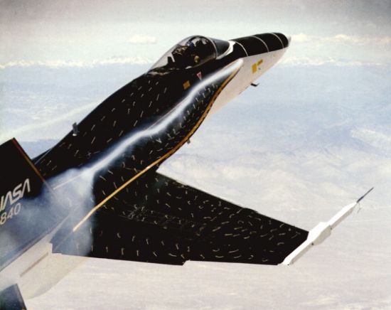
So forgive me for my humor, and in the first picture we see the Levcon vortice does not attaché to the general airflow above the wing, but at the 20 to 25 degree angle of attack projected the vortice like a tornado is aboving the wing sucking air molecules off the low pressure area on top of that wing, further lowering the pressure on top of the wing and creating more lift?? no doubt that much is also simple, it also is likely causing the verts to buffet, one of the reasons for their extremely small size in addition to adding to low-observability.
If we continue to increase the angle of attack, we will begin to have separation or departure at the trailing edge of the wing and it will progressively move forward and into and disrupt the low air pressure flow above the wing causing the wing to loss lift or "stall"?


well i got it from a video, documentry of some sorts, looks like the channel is rostec tv

Please, Log in or Register to view URLs content!
 

Air Force Brat

Brigadier
Super Moderator
excellent documentry

It is indeed an excellent documentary, but as wonderful as cad/cam is, it did not predict the cracking and structural failures that both Sukhoi and Lockheed have had to deal with on the T-50 and F-35 prototypes respectively. It is a fabulous tool, but the test article must be built and applied to fully engineer and test something so intricate and nuanced as a fifth gen or even fourth gen fighter, while air is a fluid and the old expression is lighter than air? the atmosphere becomes a brutal environment once the airspeed creeps up past 200mph or so. Those internal structures and wings take a beating, and that becomes very clear once flight test goes to work on "breaking" an aircraft. I would stress as well that heating is also a very large factor, as your high altitude aircraft may operate in a "brutally cold environment", while the aircraft itself may have expanded due to high heat, not to mention the very low atmospheric pressures that the aircraft must protect the pilot and passengers from???
 

aksha

Captain
It is indeed an excellent documentary, but as wonderful as cad/cam is, it did not predict the cracking and structural failures that both Sukhoi and Lockheed have had to deal with on the T-50 and F-35 prototypes respectively. It is a fabulous tool, but the test article must be built and applied to fully engineer and test something so intricate and nuanced as a fifth gen or even fourth gen fighter, while air is a fluid and the old expression is lighter than air? the atmosphere becomes a brutal environment once the airspeed creeps up past 200mph or so. Those internal structures and wings take a beating, and that becomes very clear once flight test goes to work on "breaking" an aircraft. I would stress as well that heating is also a very large factor, as your high altitude aircraft may operate in a "brutally cold environment", while the aircraft itself may have expanded due to high heat, not to mention the very low atmospheric pressures that the aircraft must protect the pilot and passengers from???


all the same these technologies save time , moneyand lives to some extent.

using the tejas (about which i know well) as an example (see https://www.sinodefenceforum.com/hal-tejas-jet-fighter.t4721/page-29#post-334837 , sewhich was developed using these methods,cond video from 7:10 onwards)

you will see that inspite of it being being made by india, a country which had no previous experience in indegenously developing and building any aircraft ,

it has never crashed,never came close to it, and its 15 years after its first flight
(ignoring its other problems,most of which has been caused by because of the IAF changing goalposts)

the test pilots have said it performs exactly as the computers predict in almost every parameters.

it is triumph of these technologies

but like everything it these technologies have their drawback as well.

for example, LCA navy overperformed in some parameters after the ski jump trials , and the designers have gone back to redisigning some things ,saying too much of anything is not good????


nothing is perfect but i beleive these technologies will be used in designing almost every future plane
 
Last edited:

aksha

Captain
to edit the previous post, see the first video as well as the second one(from 7:10 onwards)

note:i used the tejas only as an example and have ,no intention for off topicing


@Air Force Brat ,thought the following links (2 links are given below) may interest you, although this link is a study for another fighter and is for LEVCON's
i am assuming that LEVCONS and LERX (PAK FA) are analogues and have similar fucntions.
comparison structural
LERX (PAK FA)
LlzkDfD.jpg


LEVCONS
8e2pL3P.jpg


Please, Log in or Register to view URLs content!

An experimental and numerical investigation of high alpha aerodynamics is reported for a generic compound delta wing fighter aircraft configuration in transonic Mach number regime. The aircraft considered here is a wing-fuselage-vertical fin tailless compound delta configuration with lower inboard and higher outboard sweeps and a close combat missile outboard. The basic configuration does not have any leading or trailing edge devices such as slats and flaps. This configuration is studied first to understand the flow physics causing pitch up phenomenon for the basic configuration. Subsequently, the use of leading edge vortex controller (LEVCON) is studied for controlling pitch up. Both Computational Fluid Dynamics (CFD) and wind tunnel experiments have been used to describe the flow physics.


a person ,and he resident expert, at BR said this using the above article ,but about a different fighter, i quote him

As is evidenced from the abstract, it is clear that the CFD analysis is on the plane minus the leading edge slats. However it is acknowledged that a multi-slat configuration is used to control the vortex dynamics at higher angles of attack (Unfortunately, I cannot access the cited document as it is an internal ADA report).

In the paper, the range of AoA is normalized to between 0 and 14. Everything in the rest of the paper and in this post is with respect to this normalized AoA. By studying the C-L curve and the rolling-moment curve against the normalized AoA, it is noticeable that the present configuration (without the multi-slat configuration) has both loss and gain in lift near the pitch-up region (about 6 degrees).

After the CFD has been refined using actual testing data, it is clear why the above phenomenon occurs. Up to 4 degree AOA, the airflow from the inner sweep region of the wing does not combine with the flow from the outer sweep region. However, at about 4 degree AoA, the flow from the inner sweep region starts to curl more and interact with the vortex of the outerpart of the wing, energizeing the later. This delays the vortex bursting. None the less, like any other vortex core, tis cores expands too. It starts becoming visible on the top part of the wing at about 5 degree AoA, and is clearly visible at 6 degrees AoA.

With the Levcons, they can affect the effective AoA of the inner sweep region of the wing. By deflecting it downwards, the effective AoA at the apex region is lowered and the curling is minimized. The flow continues energetically straight down the wing and the wing-body join. However, the lack of the interaction of the flows means that the vortex from the outer sweep region of the wing breaks down (shows what would have happened if the LCA had just a delta wing like the Mig-21). The higher the LEVCON deflections better the flow quality in wing inboard region at high angles of attack. At 30 degree deflection, they can completely mitigate the pitch-up tendency. This better flow in the inboard section compensates for the loss of lift due to the vortex breakdown. The LEVCON also improves the directional stability (the limiting factor of LCA's max AoA) of the aircraft by improving flow near fin region.


you might like these too
Please, Log in or Register to view URLs content!

introduction on it
6. Aerodynamics of 3D Lifting Surfaces through Vortex Lattice Methods
6.1 An Introduction
There is a method that is similar to panel methods but very easy to use and capable of providing remarkable insight into wing aerodynamics and component interaction. It is the vortex lattice method (vlm), and was among the earliest methods utilizing computers to actually assist aerodynamicists in estimating aircraft aerodynamics. Vortex lattice methods are based on solutions to Laplace’s Equation, and are subject to the same basic theoretical restrictions that apply to panel methods.
As a comparison, vortex lattice methods are:
Similar to Panel methods: • singularities are placed on a surface • the non-penetration condition is satisfied at a number of control points • a system of linear algebraic equations is solved to determine singularity strengths Different from Panel methods: • Oriented toward lifting effects, and classical formulations ignore thickness • Boundary conditions (BCs) are applied on a mean surface, not the actual surface (not an exact solution of Laplace’s equation over a body, but embodies some additional approximations, i.e., together with the first item, we find ∆Cp, not Cpupper and Cplower) • Singularities are not distributed over the entire surface • Oriented toward combinations of thin lifting surfaces (recall Panel methods had no limitations on thickness).
Vortex lattice methods were first formulated in the late ’30s, and the method was first called “Vortex Lattice” in 1943 by Faulkner. The concept is extremely simple, but because of its purely numerical approach (i.e., no answers are available at all without finding the numerical solution of a matrix too large for routine hand calculation) practical applications awaited sufficient development of computers—the early ’60s saw widespread adoption of the method. A workshop was devoted to these methods at NASA in the mid ’70s.1 A nearly universal standard for vortex lattice predictions was established by a code developed at NASA Langley (the various versions were available prior to the report dates): Margason & Lamar2 1st Langley report NASA TN D-6142 1971 Lamar & Gloss3 2nd " " NASA TN D-7921 1975 Lamar & Herbert4,5 3rd " " NASA TM 83303 1982
 
Last edited:

Air Force Brat

Brigadier
Super Moderator
to edit the previous post, see the first video as well as the second one(from 7:10 onwards)

note:i used the tejas only as an example and have ,no intention for off topicing


@Air Force Brat ,thought the following links (2 links are given below) may interest you, although this link is a study for another fighter and is for LEVCON's
i am assuming that LEVCONS and LERX (PAK FA) are analogues and have similar fucntions.
comparison structural
LERX (PAK FA)
LlzkDfD.jpg


LEVCONS
8e2pL3P.jpg


Please, Log in or Register to view URLs content!


a person ,and he resident expert, at BR said this using the above article ,but about a different fighter, i quote him


you might like these too
Please, Log in or Register to view URLs content!

introduction on it
I couldn't load the first video, but the second I have seen, and you are right, and your little aerodynamic write up and analysis is spot on. The Levcons or LERX are indeed they same, and the Levcons serve the same function as canards on a more conventional configuration, so while all of these airplanes are faboulous and they are, these designs are very much the industry standard, which the Russian video seems to kind of ignore.

I believe vortex bursting is one of the primary reasons that Dr. Song insisted the canards on the J-20 were to be distant coupled, and decoupling that primary or first main vortex from the outer reaches of the main wing, as the Levcon is deflected downward it in effect increases the camber of that section of wing, prevent the violent and often uncontrollable "pitch up" that was the bain of early deltas.
 

b787

Captain
i am assuming that LEVCONS and LERX (PAK FA) are analogues
PAKFA has no LERX, it has LEVCONs, the LERX stand for Leading edge root extensions and LEVCON by Leading edge Vortex control.

PAKFA was the first aircraft to fly with LEVCONs as we know them
 

b787

Captain
I couldn't load the first video, but the second I have seen, and you are right, and your little aerodynamic write up and analysis is spot on. The Levcons or LERX are indeed they same, and the Levcons serve the same function as canards on a more conventional configuration, so while all of these airplanes are faboulous and they are, these designs are very much the industry standard, which the Russian video seems to kind of ignore.

I believe vortex bursting is one of the primary reasons that Dr. Song insisted the canards on the J-20 were to be distant coupled, and decoupling that primary or first main vortex from the outer reaches of the main wing, as the Levcon is deflected downward it in effect increases the camber of that section of wing, prevent the violent and often uncontrollable "pitch up" that was the bain of early deltas.
LERX and LEVCONs are not the same, they are as different as the fixed canards of Kfir are to the fully moveable foreplanes of Rafale
 

Ultra

Junior Member
to edit the previous post, see the first video as well as the second one(from 7:10 onwards)

note:i used the tejas only as an example and have ,no intention for off topicing


@Air Force Brat ,thought the following links (2 links are given below) may interest you, although this link is a study for another fighter and is for LEVCON's
i am assuming that LEVCONS and LERX (PAK FA) are analogues and have similar fucntions.
comparison structural
LERX (PAK FA)
LlzkDfD.jpg


LEVCONS
8e2pL3P.jpg


Please, Log in or Register to view URLs content!


The Levcons or LERX are indeed they same, and the Levcons serve the same function as canards on a more conventional configuration, so while all of these airplanes are faboulous and they are, these designs are very much the industry standard, which the Russian video seems to kind of ignore.


Huh?
LEVCON and LERX are NOT the same.

This is LERX:

300px-Leadingedgeextensions_annotated.svg.png

The most prominent being the F-18 example, you can even see the vortex bursting:
f18_46.jpg

The main characteristic of LERX is it is NON-MOVING, STATIC PIECE OF GEOMETRY.


Now LEVCON is completely different. It is a MOVING PIECE OF GEOMETRY, much like the canard, except it is moved backwards to the root of the wings. It is basically a stealthier version of canard.

173180510_Diff_Levcon_122_481lo.jpg

Both of your examples of T-50 and LCA should actually be termed LEVCON. The PAK-FA is the world's first actual use of LEVCON, and LCA being the close second.
 
Last edited:

b787

Captain
Huh?
LEVCON and LERX are NOT the same.

This is LERX:

300px-Leadingedgeextensions_annotated.svg.png

The most prominent being the F-18 example, you can even see the vortex bursting:
f18_46.jpg

The main characteristic of LERX is it is NON-MOVING, STATIC PIECE OF GEOMETRY.


Now LEVCON is completely different. It is a MOVING PIECE OF GEOMETRY, much like the canard, except it is moved backwards to the root of the wings.

173180510_Diff_Levcon_122_481lo.jpg
what impressive aerodynamics have PAKFA, truely a very well thought machine in terms of aerodynamics, i think this machine its truely revolutionary
 
Top