
You are using an out of date browser. It may not display this or other websites correctly.
You should upgrade or use an alternative browser.
You should upgrade or use an alternative browser.
J-10 Thread IV
- Thread starter Jeff Head
- Start date


asif iqbal
Lieutenant General
Ok so finally J10C is using indigenous engine ?
Do we have consensus on that
Do we have consensus on that
manqiangrexue
Brigadier
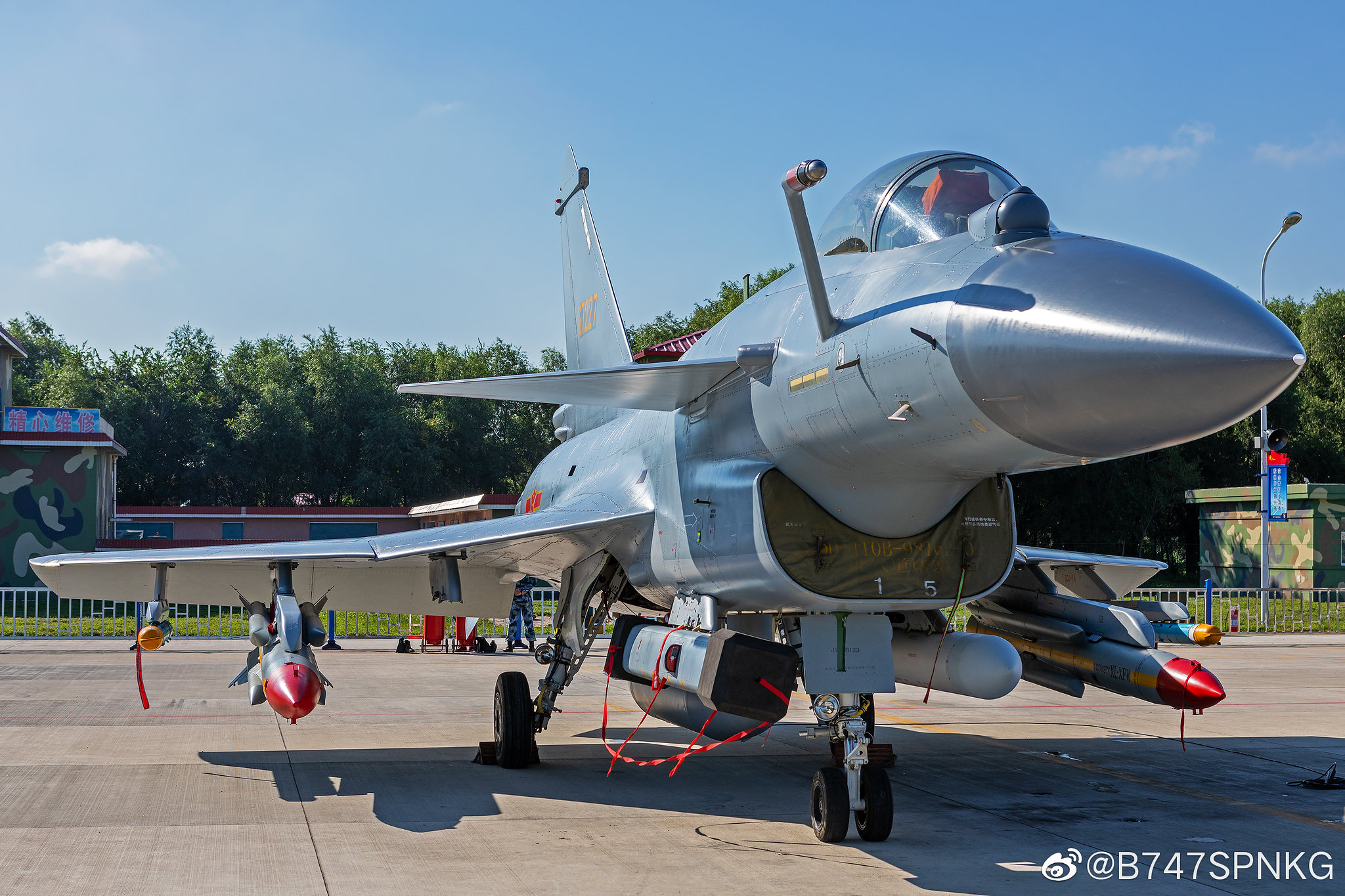
Huh? Those ones pictured are AL-31(FN3). We're definitely not in the near term going to see all J-10C with WS-10X because many have already been made with AL-31. Maybe they'll get an engine swap during MLU but the PLA is certainly not going to rip perfectly good Russian engines out to install WS-10X for the sake of indigenization. So we will still see most J-10C with AL-31 but the more recent ones are said to be using WS-10X.Ok so finally J10C is using indigenous engine ?
Do we have consensus on that
Hyperwarp
Captain
Ok so finally J10C is using indigenous engine ?
Do we have consensus on that
 All images show AL-31FN
asif iqbal
Lieutenant General
I am not talking about the above photos
I am taking about batch 4
I am taking about batch 4
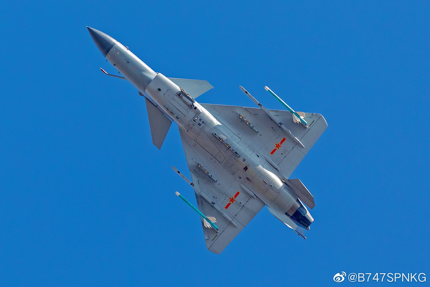
J-16 supposedly reduced the flanker RCS dramatically (clean layout) just by using a RAM surface treatment. But it is still a large bird and has engine fan exposed completely. It may be considered 4.5 gen in every other respect but the J-10b/c will still have a lower RCS purely due to smaller size and hidden engine face + DSI intakes. If the electronics, sensor suite, and software are all up to the J-16's level, they should also be considered 4.5 gen. I'd say DSI, hidden engine, and the apparent improvement on surface quality can all be considered efforts to reduce RCS although it isn't taking it to the Typhoon and Rafale's level with serrated edges or J-16's RAM paint.
You can see it right here in this picture that was already posted.

At the front, the radar would pass through the radome and hit the plane's radar. If the J-10's radar's face is set straight, like it was in the original, the signals from the threat radar would bounce directly back to the threat. But the J-10B & C's AESA is set at an inclined rest angle, the signals would bounce up and not towards the other radar.
Radar signals would also be bouncing at the firewall separating the radar and the back end. In here, the firewall itself is angled. That's more bounce away in an angle.
Another area of bounce would be the rim of the radome, the seam between the radome and the metal. On the previous J-10, like the firewall, it would be straight. On the angled radome, the rim around the radar would also be angled to bounce upwards.
You don't want this. Firewall, radar, the radome rim, all straight.

You want this. The radar, the wall behind it, the rim around it, all angled.


Another area of radar bounce would be the rim that makes up the intake. The original J-10's boxy and straight intake would bounce radar waves back. Here, the intake is angled to bounce upward. Note the angle of the diverter intake's rim and the rim of the radome has the same angle. That's intentional, so the radar that is bouncing off on both is towards the same upward direction. You want less directions to scatter radar around.
The DSI intake further bounces radar waves away from the engine intake.
There are things that still need to improvement however. Most notably is the circular rim in front of the cockpit over the hud. Refueling probe doesn't help either. And there is always that tall vertical tail. But from a head on perspective, RCS would be reduced from the angled radar, firewall, the rim around it, as well on the angled rim of the diverter intake and from the DSI itself.

I am not talking about the above photos
I am taking about batch 4
I think so, but so far we haven't seen any clear images.
You can see it right here in this picture that was already posted.
View attachment 54834
At the front, the radar would pass through the radome and hit the plane's radar. If the J-10's radar's face is set straight, like it was in the original, the signals from the threat radar would bounce directly back to the threat. But the J-10B & C's AESA is set at an inclined rest angle, the signals would bounce up and not towards the other radar.
Radar signals would also be bouncing at the firewall separating the radar and the back end. In here, the firewall itself is angled. That's more bounce away in an angle.
Another area of bounce would be the rim of the radome, the seam between the radome and the metal. On the previous J-10, like the firewall, it would be straight. On the angled radome, the rim around the radar would also be angled to bounce upwards.
You don't want this. Firewall, radar, the radome rim, all straight.
View attachment 54836
You want this. The radar, the wall behind it, the rim around it, all angled.
View attachment 54838 View attachment 54839
Another area of radar bounce would be the rim that makes up the intake. The original J-10's boxy and straight intake would bounce radar waves back. Here, the intake is angled to bounce upward. Note the angle of the diverter intake's rim and the rim of the radome has the same angle. That's intentional, so the radar that is bouncing off on both is towards the same upward direction. You want less directions to scatter radar around.
The DSI intake further bounces radar waves away from the engine intake.
There are things that still need to improvement however. Most notably is the circular rim in front of the cockpit over the hud. Refueling probe doesn't help either. And there is always that tall vertical tail. But from a head on perspective, RCS would be reduced from the angled radar, firewall, the rim around it, as well on the angled rim of the diverter intake and from the DSI itself.
View attachment 54835
Thanks for the input. It's always been clear to me that from B changes onwards, the J-10 was clearly designed to improve the RCS on the J-10A, among other areas. J-16 has almost no structural improvement to reduce RCS except for the obvious ones; RAM and even the cockpit seems to use a similar grey colour. Overall I don't doubt the J-10B/C has far lower RCS than J-16. J-10C also seems to feature the same tinted canopy. It's not the same or as obvious as the J-20's but it's quite obviously there. The only question is why CAC didn't work J-16's RAM paint into the newest J-10 variants.