Chinese Radar Developments - KLJ series and others

Hyperwarp

Captain
Regarding the Type 1760 -
Please, Log in or Register to view URLs content!


Don't know about the reliability. Does anyone have the original research paper?

All slides -
Please, Log in or Register to view URLs content!


According to the last slide the 1760 can hit 250 km for 0.1 m^2 target. So, that would roughly mean,
Rc/Rn = (Sc/Sn) ^ 0.25
250/Rn = ((0.1/0.01)^0.25)
Rn = ~140 km

* Thats 140 km for 0.01 m^2 target :eek::eek:
* I remember another post with a similar table for the J-20 radar and after the calulations, the value came to (at peak) 170 km per 0.01 m^2 target :eek::eek::eek:

Now the simple question is, can anyone verify this?
 

Brumby

Major
Think it’s actually the other way around...the J-10 is a bigger plane than the F-16. I seem to recall someone measuring the nose of the two before, but if not this is a point that can be verified with data.
It was just an assumption that I made that their respective aperture size is somewhat similar. If my assumption is not right then I am happy to be corrected with better data.
It’s also worth noting that KLJ-7A, intended for export and use on the JF-17, is listed as having a 170km detection range for 3 m^2 targets. I’m not sure what baseline the F-16 figure you cited is using, but if it’s the same baseline that would mean that the KLJ-7A has roughly the same (or slightly better) performance, which would imply that we can’t simply make an apples to apples comparison based on array size, assuming the JF-17 has a smaller nose than the F-16. (To be clear I’m not saying the JF-17 Block III’s AESA is necessarily better than the F-16’s, just the figure you cited).
A 170 km detection range against 3m2 is 129 km at 1m2. This would match the capability of APG-80 in Block 60 (I think). As to the JF-17, it is my belief that its AESA is probably a scaled down version to keep cost manageable and may not be representative of Chinese AESA meant for the other 3 platforms.
As to your F-16 baseline comment - not sure what you are referencing to.

The J-20, according to this following graphic which we received years ago, has a third generation AESA compared to the J-16’s second generation...again, we shouldn’t just assume an apples to apples comparison.

Chinese%20fighter%20AESA.jpg
I have seen them years ago. In any case, I would have no clue on how to use the information to extrapolate.
 

Brumby

Major
1. "First stab at the technology"? --- First Chinese AESAs were developed in the 1990s. The first deployed in the PLA was an artillery tracker back in the early 2000s. That must be good if you are able to detect artillery shells and trace them back to their origins. If J-16's AESA uses GaN, then it may blow performance out of the water.

2. J-20 AESA --- The earlier ones might still be using GaAs, but later ones might be or already shifting to GaN. But they are not telling.

3. No reason to believe that European standard is lower than US standard. The US may have an earlier start at AESA development in the 1990s, but the Europeans appeared to have overtaken the US in the 2000s and 2010s at least in terms of naval radars.
I was referring to AESA on fighter planes. Any reference to radar on land or at sea is totally irrelevant due to space, weight and cooling issues specific to fighter planes
 

Tam

Brigadier
Registered Member
I was referring to AESA on fighter planes. Any reference to radar on land or at sea is totally irrelevant due to space, weight and cooling issues specific to fighter planes

J-16 won't be the first time you see an AESA on a Chinese plane. The first would have been on the J-10B, which was completed in 2008. Other AESAs are on satellites, AEW planes, such as KJ-2000, KJ-200, KJ-500. In terms of fighter radars, after the J-10B, there was the J-10C and the J-11D, as well as the radar intended to upgrade the J-11B.

Are you suggesting that the Chinese don't know anything involved with electronics cooling? Or don't know how to make light, compact electronics?

All AESAs generate heat and have power limits that is due to the physical limits of GaAs or Gallium Arsenide semiconductor. There are packaging and subarray innovations to help transfer the heat away, or using air or liquid cooling. But these are ultimately just band aid to the real problem. The real problem is simply the limits of Gallium Arsenide, and the move to the next generation is the use of Gallium Nitride or GaN, whether the application is aerial, naval, land or space. The ability to harness and develop GaN based AESAs, whether on air. land, sea or space, will eventually and quickly lead to all other applications whether on air, land, sea or space. GaN delivers more power for less heat, is lighter, is cheaper, and is more sensitive.

The shift to GaAs to GaN is already happening across the globe, and the real question you should be asking if the J-16's AESA radar would be using GaN or not? 2015 to 2020 is the transition era where the earlier generation of GaAs based AESAs will give way to the next generation of GaN based AESAs.

Defining first, second or third generation in AESA is extremely vague without a goal point, but the difference between GaAs and GaN in AESA is very real, and probably the one that really matters.
 

Tirdent

Junior Member
Registered Member
PESA will surely have less receiving and transmit gain. There is going to be signal losses between the travel path of the main amp to the emitters in the elements. This includes the line feeds and duplexers in the sub array level, and then between the phase shifters themselves. That's for the transmit part. On the receive part, there is going to be signal losses between the receiving element to the A/D converters, as there is more path between the receiver to the A/D converter which is located way more downstream on the PESA, perhaps at the subarray level.

You CAN think of gain that way and assume transmitter power to be the same instead, but I prefer not to because it's a bit misleading in terms of the underlying physics. The principle of slit diffraction to form the radiation pattern is fundamentally the same for both AESA and PESA (and really even slot array) antennas so it seems more logical to attribute the difference to the transmitter and consider it a penalty on radiated power for the PESA.

From this point of view, gain is determined by antenna diameter and frequency: the spacing between individual radiating elements in a planar array (whether those are full-blown TRMs in an AESA, phase shifters in a PESA or just slots in a mechanically scanned radar) is defined by wave length and the total number which can fit on the antenna by its dimensions. Two systems that are both ~0.9m in diameter and both operate in X-band are therefore by definition going to be very close in this regard. Where an AESA has an advantage is effective radiated (as opposed to transmitter) power due to losses between the TWT and antenna face, for all the reasons you mention, but as I said it's probably more accurate to think of gain as a measure of "antenna directivity", how well it focuses the RF energy in the desired direction. Typically there is a similar advantage over PESAs on the receiver end, but the Bars & Irbis have AESA-style distributed receivers, so it doesn't apply in this case (it is much easier to do in the receive path as signal power level is far lower, so waste heat is acceptable even with less advanced microelectronics manufacturing).

Other AESA advantages (using subdivisions of the array independently, spread spectrum techniques etc.) give very major advantages in LPI and ECCM, but are unrelated to the question of maximum range.
 
Last edited:

Tam

Brigadier
Registered Member
You CAN think of gain that way and assume transmitter power to be the same instead, but I prefer not to because it's a bit misleading in terms of the underlying physics. The principle of slit diffraction to form the radiation pattern is fundamentally the same for both AESA and PESA (and really even slot array) antennas so it seems more logical to attribute the difference to the transmitter and consider it a penalty on radiated power for the PESA.

Its not the slit diffraction. Its the feed between the amp to the emitter. For the PESA, the amp is further way down or way down further from the emitters. This is where most of the losses comes from. This happens whether you have a spaced or optical feed PESA, or if you have a parallel line feed PESA.

From this point of view, gain is determined by antenna diameter and frequency: the spacing between individual radiating elements in a planar array (whether those are full-blown TRMs in an AESA, phase shifters in a PESA or just slots in a mechanically scanned radar) is defined by wave length and the total number which can fit on the antenna by its dimensions. Two systems that are both ~0.9m in diameter and both operate in X-band are therefore by definition going to be very close in this regard. Where an AESA has an advantage is effective radiated (as opposed to transmitter) power due to losses between the TWT and antenna face, for all the reasons you mention, but as I said it's probably more accurate to think of gain as a measure of "antenna directivity", how well it focuses the RF energy in the desired direction. Typically there is a similar advantage over PESAs on the receiver end, but the Bars & Irbis have AESA-style distributed receivers, so it doesn't apply in this case (it is much easier to do in the receive path as signal power level is far lower, so waste heat is acceptable even with less advanced microelectronics manufacturing).

Other AESA advantages (using subdivisions of the array independently, spread spectrum techniques etc.) give very major advantages in LPI and ECCM, but are unrelated to the question of maximum range.

AESA and PESA require about 1/2 wavelength spacing or you will face grating lobes.

Receiver db loss on PESA is also due because the A/D converter for PESA is way further down from the array in the subarray level. In comparison, the A/D converter on AESA is right on the module itself. This means the analog signal as received is converted to a digital input right in the module instead, instead of incurring losses as the analog signal has to travel down to the subarray level before it can be converted to a digital input.
 

Tam

Brigadier
Registered Member
Typically there is a similar advantage over PESAs on the receiver end, but the Bars & Irbis have AESA-style distributed receivers, so it doesn't apply in this case (it is much easier to do in the receive path as signal power level is far lower, so waste heat is acceptable even with less advanced microelectronics manufacturing).

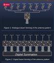
Typically, the path setup from the receiver to the A/D converter on a PESA or mechanical array is like the top one here. The bottom is more like the way AESA works. You get losses on the signal as it travels down further along the way before it gets to the A/D converter. The shorter the path the better. The bottom setup can be done either right on the module itself, or in the subarray level, where one A/D converter handles a series or small set of modules. Do note if its on the module, there are TRMs (one T/R per module), DTRMs (Dual T/R per module) and QTRMs (Quad T/R per module). BARS or IRBIS might be doing something like this in the sub array level like the second one, the better for them in doing this, though not one T/R per A/D converter, but small sets of T/R in the subarray level being connected to a single A/D converter in a distributed approach, rather than the entire array of receivers being connected to a single A/D converter.

Screenshot 2019-04-03 at 11.08.16 AM.png
 
Last edited:

Anlsvrthng

Captain
Registered Member
J-16 won't be the first time you see an AESA on a Chinese plane. The first would have been on the J-10B, which was completed in 2008. Other AESAs are on satellites, AEW planes, such as KJ-2000, KJ-200, KJ-500. In terms of fighter radars, after the J-10B, there was the J-10C and the J-11D, as well as the radar intended to upgrade the J-11B.

Are you suggesting that the Chinese don't know anything involved with electronics cooling? Or don't know how to make light, compact electronics?

All AESAs generate heat and have power limits that is due to the physical limits of GaAs or Gallium Arsenide semiconductor. There are packaging and subarray innovations to help transfer the heat away, or using air or liquid cooling. But these are ultimately just band aid to the real problem. The real problem is simply the limits of Gallium Arsenide, and the move to the next generation is the use of Gallium Nitride or GaN, whether the application is aerial, naval, land or space. The ability to harness and develop GaN based AESAs, whether on air. land, sea or space, will eventually and quickly lead to all other applications whether on air, land, sea or space. GaN delivers more power for less heat, is lighter, is cheaper, and is more sensitive.

The shift to GaAs to GaN is already happening across the globe, and the real question you should be asking if the J-16's AESA radar would be using GaN or not? 2015 to 2020 is the transition era where the earlier generation of GaAs based AESAs will give way to the next generation of GaN based AESAs.

Defining first, second or third generation in AESA is extremely vague without a goal point, but the difference between GaAs and GaN in AESA is very real, and probably the one that really matters.

Please, Log in or Register to view URLs content!

However, what differentiates Raytheon from the other offerors is that it began investing in GaN 20 years ago, when hardly anybody had heard of it. Over the intervening years it has spent $300 million developing a deep understanding of the technology, including building its own GaN foundry and a prototyping facility in New Hampshire that tests radar resilience and reliability in highly stressed conditions.

300 million investment doesn't sound something that China, Russia or even Spain can't afford into the technology.


So, any advantage gained from GaN disappeared in the past years, or will disappear before 20s.

After all that left is the size / cooling capacity differences, and the experience with the software .

In the latest the Russians had a clear advantage, in the later the USA has a clear disadvantage compared to Ru/Cn
 
Last edited:

Anlsvrthng

Captain
Registered Member
Its not the slit diffraction. Its the feed between the amp to the emitter. For the PESA, the amp is further way down or way down further from the emitters. This is where most of the losses comes from. This happens whether you have a spaced or optical feed PESA, or if you have a parallel line feed PESA.


AESA and PESA require about 1/2 wavelength spacing or you will face grating lobes.

Receiver db loss on PESA is also due because the A/D converter for PESA is way further down from the array in the subarray level. In comparison, the A/D converter on AESA is right on the module itself. This means the analog signal as received is converted to a digital input right in the module instead, instead of incurring losses as the analog signal has to travel down to the subarray level before it can be converted to a digital input.
The correct physical description of the ESA is slit diffraction.

Whatever happens down on the feed is technical matters,and affect only the amount of radiated energy.

The laser + slit generated diffraction pattern happens exactly by the same way as the PESA radar transmission.
 

Tam

Brigadier
Registered Member
The correct physical description of the ESA is slit diffraction.

Whatever happens down on the feed is technical matters,and affect only the amount of radiated energy.

The laser + slit generated diffraction pattern happens exactly by the same way as the PESA radar transmission.

Not talking about slit diffraction, which you can also call frequency steering --- change of frequency of a radio wave going through a slot changes its direction.

I am talking about the signal loss between the main amp and the emitting array. Signal loss and distortion between main amp and emitters by signal travelling through line path is significant enough, that its one of the reasons justifying AESA development.

Going back to frequency steering or "squint" in short, what changes the frequency is the delay of the signal between the amp to the emitter. This is why the lines from the main amp to the emitters must be of the same length.
 
Top